High-power permanent magnet synchronous generator

A permanent magnet synchronous and generator technology, applied in synchronous machines, synchronous machine parts, electrical components, etc., can solve the problems of increasing the volume of the generator, increasing the amount of permanent magnets, and increasing the cost of the generator, so as to ensure the magnetic energy product. , the effect of prolonging life

Active Publication Date: 2011-08-17
东元总合科技(杭州)有限公司
View PDF4 Cites 10 Cited by
  • Summary
  • Abstract
  • Description
  • Claims
  • Application Information

AI Technical Summary

Problems solved by technology

Increasing the length of the air gap is to weaken the demagnetization flux generated by the generator overload operation, sudden short circuit, etc., but it will inevitably weaken the back EMF, output power and other performance of the generator; increasing the thickness of the permanent ma

Method used


Image

  • High-power permanent magnet synchronous generator
  • High-power permanent magnet synchronous generator
  • High-power permanent magnet synchronous generator

Examples


Embodiment approach

[0054] see Figure 8 , the second embodiment of the present invention. In this embodiment, under abnormal operating conditions such as generator overload operation and sudden short circuit, the two permanent magnets passing through or closest to the center of each pole of the rotor are at the maximum demagnetization field strength of each pole. The magnet 1 gap is described. The auxiliary mechanism in this embodiment is the permanent magnet 7 arranged in the rotor core at the above-mentioned gap position, and the permanent magnet 7 penetrates the entire rotor core 2 along the rotor axial direction.

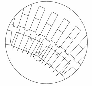
[0055] see Figure 9 , taking one pole of the rotor as an illustration. The side of the permanent magnet 1 of the rotor pole away from the rotor axis is the N pole, and the side close to the rotor core 2 is the S pole. Abnormal operations such as overload operation and sudden short circuit of the generator The direction of the demagnetizing magnetic field generated in the state ...


PUM


Abstract

The invention provides a high-power permanent magnet synchronous generator, which aims to solve the problem that permanent magnets of a rotor of the high-power permanent magnet synchronous generator with a surface-mounted permanent magnet structure may easily produce partial permanent demagnetization due to a demagnetized field produced under the conditions of overload running, sudden short circuiting and the like. At least an auxiliary mechanism is arranged on the rotor of the generator, and weakens demagnetized field intensity at positions, axially clinging to the two edges of a rotor core along the generator, of two adjacent permanent magnets. The high-power permanent magnet synchronous generator avoids the permanent demagnetization of the permanent magnets of the rotor under the abnormal running conditions of overload running, sudden short circuiting and the like of the generator, so the magnetic energy product of the permanent magnets is ensured, and simultaneously, the service life of the generator is prolonged.

Description

technical field [0001] The invention relates to the technical field of permanent magnet synchronous generators, in particular to a high-power permanent magnet synchronous generator whose rotor adopts a surface-mounted permanent magnet structure. Background technique [0002] Permanent magnet motors have the advantages of low loss and high efficiency, and are used more and more widely today when energy conservation and environmental protection are increasingly valued. For applications such as fans, pumps, compressors, etc. that operate at a continuous, constant speed and in one direction, ordinary asynchronous motors are gradually being replaced by permanent magnet motors due to the waste of electric energy caused by efficiency, power factor and other reasons. At the same time, the operating speed of many industrial machines needs to be set and adjusted arbitrarily, but the accuracy of speed control is not high. Due to the advantages of small size, high efficiency and energy ...

Claims


Application Information

Patent Timeline
IPC IPC(8): H02K21/00H02K1/27H02K21/02
Inventor 黄越周俊
Owner 东元总合科技(杭州)有限公司
Why Eureka
Try Eureka