
Permanent magnet motor rotor permanent magnet temperature real-time monitoring method and model

A permanent magnet motor and real-time monitoring technology, which is applied in the control purpose model/simulation, motor control, electrical components, etc., can solve the problems of reducing the accuracy of the model, increasing the difficulty of modeling, and the difficulty of modeling

Pending Publication Date: 2021-01-15
盖耀辉
View PDF0 Cites 0 Cited by
  • Summary
  • Abstract
  • Description
  • Claims
  • Application Information

AI Technical Summary

Problems solved by technology

However, this technique requires precise measurement equipment and accurate parameters of the motor and inverter. In addition, the nonlinearity of the motor caused by saturation must be considered in the modeling, which will greatly increase the difficulty of modeling and reduce the accuracy of the model.
[0006] In summary, the current technology for monitoring the operating temperature of permanent magnets has the problems of low reliability and accuracy of measurement equipment, difficulty in modeling, and low accuracy of modeling. How to effectively monitor the operating temperature of permanent magnets has become a technical problem that needs to be solved urgently

Method used


Image

  • Permanent magnet motor rotor permanent magnet temperature real-time monitoring method and model
  • Permanent magnet motor rotor permanent magnet temperature real-time monitoring method and model
  • Permanent magnet motor rotor permanent magnet temperature real-time monitoring method and model

Examples


Embodiment 1

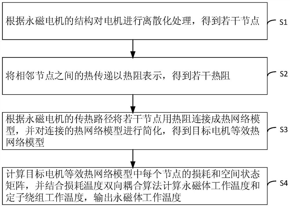
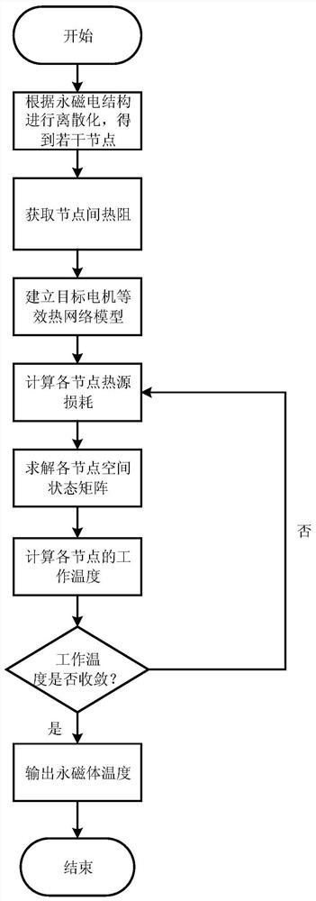
[0072] See figure 1 and figure 2 , figure 1 It is a schematic flowchart of a method for real-time monitoring of the permanent magnet temperature of the permanent magnet motor rotor provided by the embodiment of the present invention, figure 2 It is a schematic flowchart of another method for real-time monitoring of the permanent magnet temperature of the permanent magnet motor rotor provided by the embodiment of the present invention. The real-time monitoring method comprises steps:

[0073] S1. Discretize the motor according to the structure of the permanent magnet motor to obtain several nodes.

[0074] Specifically, according to the structure of the permanent magnet motor, the structure of different components in the motor is discretized, and each component is represented in the form of nodes to obtain multiple nodes, and each node is regarded as a unit with lumped parameters. For example, for the built-in permanent magnet motor, the structure of different components ...

Embodiment 2

[0113] On the basis of the first embodiment, this embodiment is described by taking the real-time monitoring method of the permanent magnet temperature of the rotor of the built-in permanent magnet synchronous motor as an example.

[0114] See Figure 4 , Figure 4 It is a schematic diagram of a target motor equivalent thermal network model of an interior permanent magnet synchronous motor provided by an embodiment of the present invention.

[0115] For the built-in permanent magnet motor, the heat generated by the loss of the permanent magnet first passes through the rotor core and then is transferred to the stator core and finally dissipates the heat through the cooling medium. Therefore, the real-time monitoring method of the rotor permanent magnet temperature of the built-in permanent magnet synchronous motor Include steps:

[0116] S1. Discretize the motor according to the structure of the permanent magnet motor to obtain several nodes.

[0117] S2. Express the heat tr...

Embodiment 3

[0141] On the basis of the first embodiment, this embodiment takes the real-time monitoring method for the temperature of the permanent magnet of the surface-mounted permanent magnet synchronous motor rotor as an example for illustration.

[0142] See Figure 5 , Figure 5 It is a schematic diagram of a target motor equivalent thermal network model of a surface-mounted permanent magnet synchronous motor provided by an embodiment of the present invention.

[0143] The only structure difference between the surface mount permanent magnet motor and the interior permanent magnet motor is the position of the permanent magnet in the rotor, which also affects the heat transfer path of the permanent magnet. For surface-mounted permanent magnet motors, permanent magnet losses are directly transferred to the cooling medium through the stator core. Therefore, the real-time monitoring method of the permanent magnet temperature of the permanent magnet synchronous motor rotor includes step...


PUM


Abstract

The invention relates to a permanent magnet motor rotor permanent magnet temperature real-time monitoring method and model. The method comprises steps of carrying out the discretization of a motor according to the structure of a permanent magnet motor, and obtaining a plurality of nodes; representing heat transfer between adjacent nodes by thermal resistance to obtain a plurality of thermal resistances; according to the heat transfer path of the permanent magnet motor, the multiple nodes being connected into a thermal network model through thermal resistance and simplified, a target motor equivalent thermal network model being obtained, in the target motor equivalent thermal network model, the heat absorption or heat dissipation capacity of each node being represented by thermal capacity,and the heat source of each node being represented by loss; and calculating a space state matrix of each node in the equivalent thermal network model of the target motor, calculating the working temperature of the permanent magnet and the working temperature of the stator winding by combining a loss temperature bidirectional coupling algorithm, and outputting the working temperature of the permanent magnet. The method can achieve real-time monitoring of the temperature of the permanent magnet of the permanent magnet motor, and guarantees calculation accuracy and reliability of the temperatureof the permanent magnet.

Description

technical field [0001] The invention belongs to the field of new energy electric vehicles, and in particular relates to a method and a model for real-time monitoring of the temperature of a permanent magnet of a rotor of a permanent magnet motor. Background technique [0002] Permanent magnet motors are gradually becoming the motor technology of choice for electric vehicle drive systems due to their high power / torque density, high efficiency, and compact size. When the motor is running, cogging and current harmonics can cause significant eddy current losses in the permanent magnets due to the relatively low resistivity of the rare earth magnets. The eddy current loss causes the temperature of the permanent magnet to rise, which will reduce the performance of the permanent magnet, and even cause irreversible demagnetization of some magnets in severe cases, shortening the service life. Therefore, in order to ensure that the permanent magnet motor operates within the specified...

Claims


Application Information

Patent Timeline
IPC IPC(8): H02P29/66H02P6/34
CPCH02P29/662H02P6/34
Inventor 盖耀辉
Owner 盖耀辉
Learn More