Connector with lever

A technology of connectors and mating connectors, which is applied in the direction of connection, parts of connection devices, coupling devices, etc., can solve the problems of increasing the size of the housing 301, and achieve the effects of reducing size, improving rigidity, and improving operating efficiency

Inactive Publication Date: 2011-08-17
MOLEX INC
View PDF6 Cites 10 Cited by
  • Summary
  • Abstract
  • Description
  • Claims
  • Application Information

AI Technical Summary

Problems solved by technology

Further, since the cover member 306 for covering the upper side of the lock arm 305 is required, the size of the housing 301 in the vertical direction will be further increased.

Method used


Image

  • Connector with lever
  • Connector with lever
  • Connector with lever

Examples


Embodiment Construction

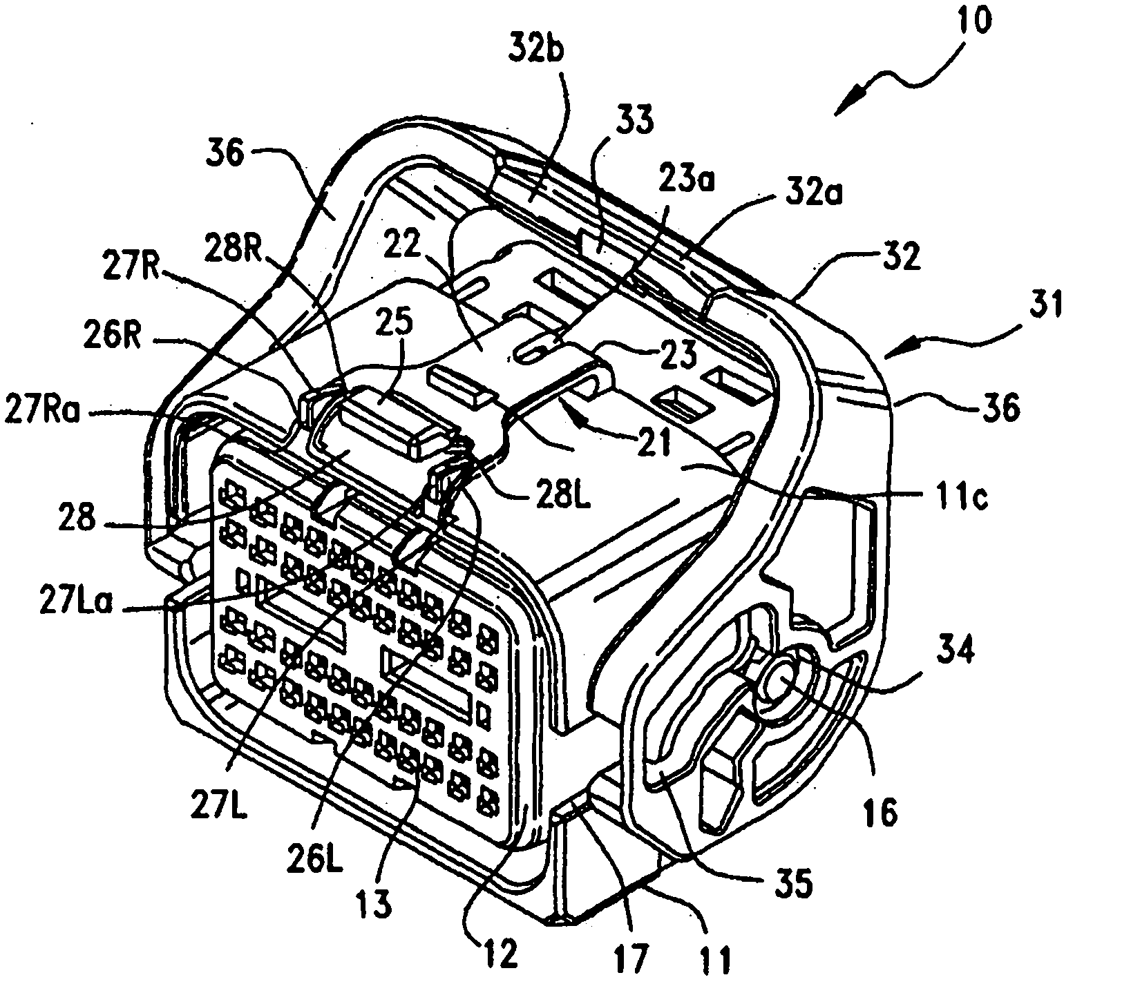
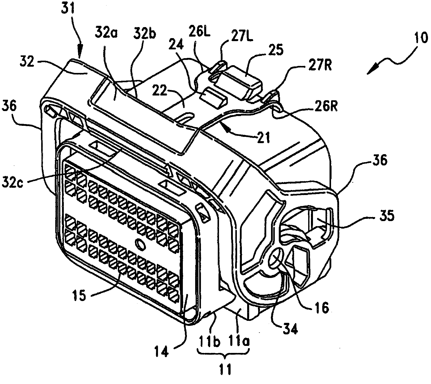
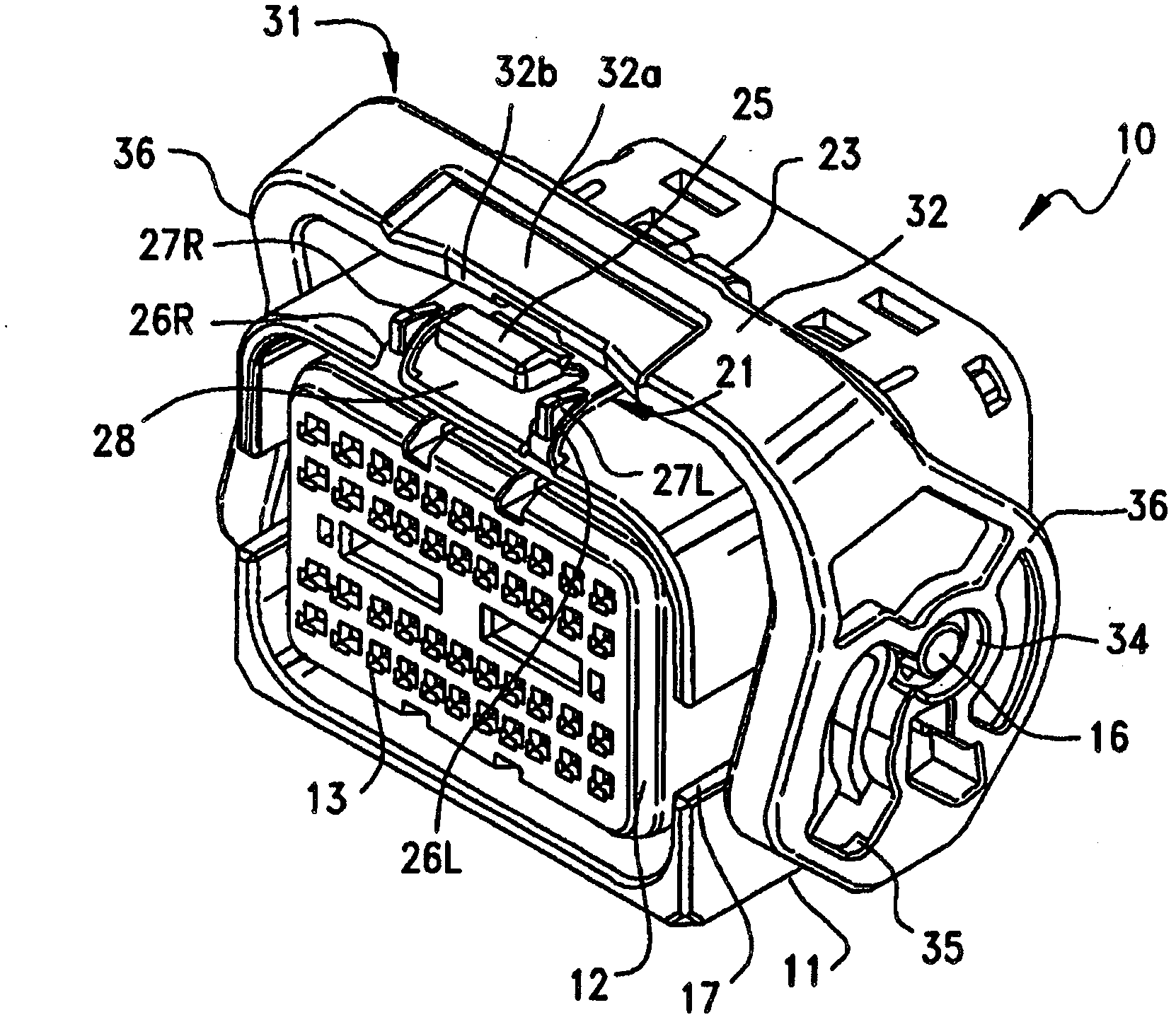
[0027] Preferred embodiments of the present invention will be described in detail below with reference to the accompanying drawings.

[0028] figure 1 is a perspective view of a side of a mating face of a connector according to an embodiment of the present invention, showing a state where the engaging lever is located at a first position; figure 2 is a perspective view of the rear surface side of the connector according to the embodiment of the present invention, which shows a state where the engaging lever is located at the first position; image 3 is a perspective view of a side of a mating face of a connector according to an embodiment of the present invention, showing a state where the engagement lever is in a second position; Figure 4 is a perspective view of the rear surface side of the connector according to the embodiment of the present invention, showing a state where the engagement lever is located at the second position.

[0029] In the drawings, reference numer...


PUM


Abstract

A connector is provided with a rotatable toggle lever which is movable between a first position where the connector is fitted to a counterpart connector and a second position in which the connector is secured to the counterpart connector. The connector includes a housing and a lock member for locking the lever at the second position. The lock member has a body portion extending approximately parallel with one wall surface of the housing. The lock member has a locking engaging projection portion for engagement with the lever and, at one end of the body, has a releasing operation portion for releasing the engagement of the projection. A first connection portion connects the other end of the body portion to the one wall surface while second connection portions are arranged on both sides of the releasing operation portion to connect the one end of the body portion to the one wall surface. The lock member further includes cable protective projections projecting from the surfaces of the second connection portions in a direction away from the one wall surface. The lever includes a cross frame portion having a concave portion formed in a position located adjacent the releasing operation portion when the lever is in the second position.

Description

technical field [0001] The invention relates to a connector with a lever. Background technique [0002] Generally, a connector fitted in a mating connector has an engaging lever including an engaging hole provided on a side wall of a housing that can accommodate electronic equipment such as a control device or various similar equipment, so that the engaging hole and the In a state where engaging protrusions provided on the housing are engaged, the connector is fitted into the mating connector with increasing fitting pressure by turning the engaging lever, see, for example, Japanese Patent Application Laid-Open No. 2005-317384. [0003] Fig. 9 is a perspective view showing a conventional connector. [0004] In this figure, reference numeral 301 denotes a housing of a conventional connector, which is made of an insulating material such as synthetic resin. In the mating surface of the housing 301 are formed a plurality of insertion openings 302 into which mating terminals of ...

Claims


Application Information

Patent Timeline
Patent Type & Authority Applications(China)
IPC IPC(8): H01R13/629H01R13/627
CPCH01R13/6295H01R13/62955H01R13/6272H01R13/62933H01R13/62938
Inventor 堀孝之
Owner MOLEX INC
Why Eureka
Try Eureka