
Vibration reducing control device

A control device and soil technology, applied in the field of plate compaction, can solve the problems of brittleness, high price, and failure to achieve vibration reduction effects.

Inactive Publication Date: 2011-08-24
BOMAG
View PDF8 Cites 4 Cited by
  • Summary
  • Abstract
  • Description
  • Claims
  • Application Information

AI Technical Summary

Problems solved by technology

[0005] The disadvantage of the above-mentioned prior art control device is that, due to its complexity, it is expensive on the one hand, and on the other hand, it cannot be freely applied to other soil compactors
Another disadvantage is the gradual aging of the elastomer due to external loads, which can lead to embrittlement and fracture, with the result that long-term reliable vibration damping cannot be guaranteed
In addition, the traditional method sometimes fails to achieve a satisfactory vibration reduction effect.

Method used

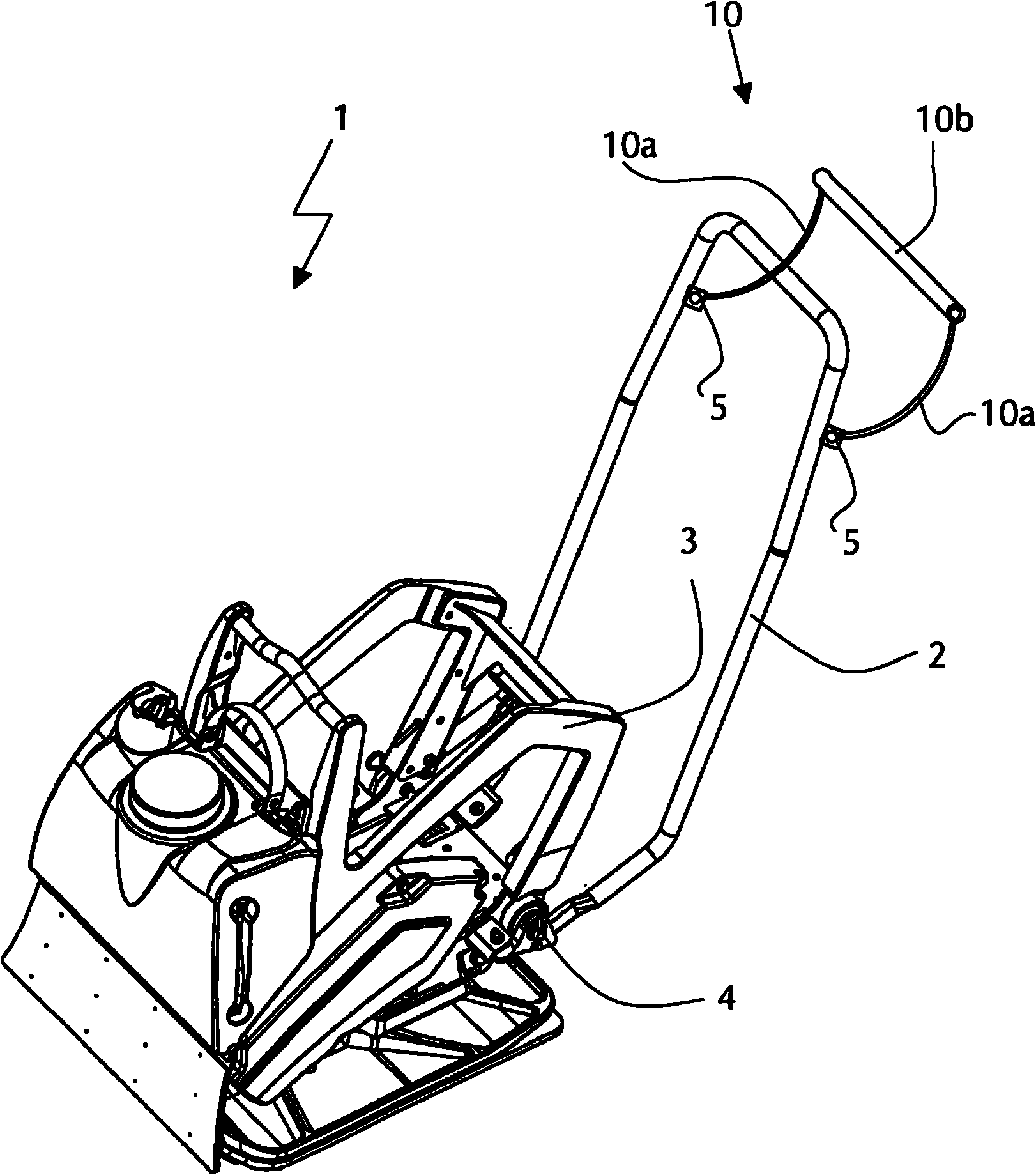
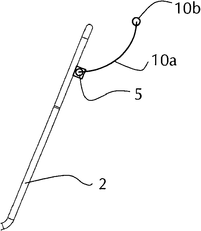
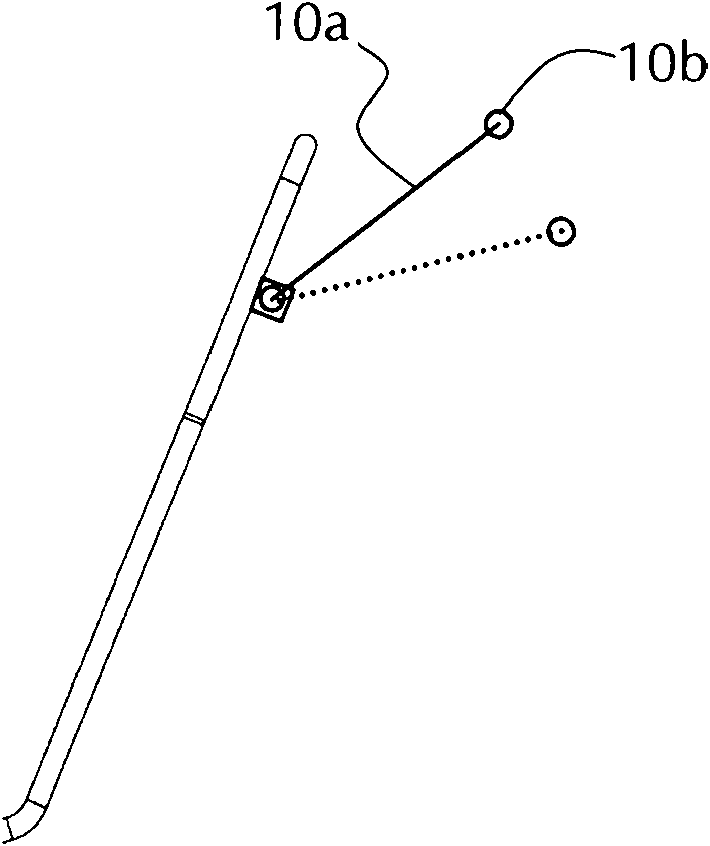

Image

  • Vibration reducing control device
  • Vibration reducing control device
  • Vibration reducing control device

Examples


Embodiment Construction

[0048] figure 1 It is a plate compactor 1 with a base 3 . The control armrest frame 2 of the plate compactor 1 is connected with the base 3 at the connection point 4 . For vibration reduction, an elastomer shock absorber (not shown) is installed between the base 3 and the control armrest frame 2 . In principle, the control armrest frame 2 can also be used as the control device of the plate compactor 1, but it cannot effectively reduce the handle transmitted from the vibrator to the control armrest frame 2 (that is, the horizontal connection between the two vertical bars of the control armrest frame 2) Vibration, vibration reduction can not achieve satisfactory results. Therefore, the control device of the present invention is fixedly installed at the connection point 5 .

[0049] according to Figure 1 In the example shown, the control device 10 of the present invention includes a plastic handle 10b and two sections of bendable plastic rope 10a. The handle 10b is connecte...


PUM


Abstract

The invention relates to a vibration reducing control device used for a manual soil compacting machine, and is particularly suitable for a plate compactor. At least a segment of the device is flexible and bendable. Such design can obviously reduce vibration transmission from an exciter to an operator. Additionally, the control device in the invention is advantaged by low production cost and simple adding.

Description

technical field [0001] The invention relates to a vibration reduction control device used on a manual soil compactor, especially suitable for plate compactors. Background technique [0002] Manual soil compactors, such as plate compactors or compactors, which are primarily used on smaller or medium jobsites, typically have a grab bar or drawbar as the control for the compactor. All processes that change the direction and speed of movement of a soil compactor are called "controlling". [0003] The vibrations generated by the exciter are transmitted to the ground being compacted and also to the controls of the compaction machine, which is disturbing for the machine operator, who must hold the handle of the controls while the machine is running. Long-term vibration disturbance can cause serious hazards to the operator's health. In order to protect the operator, manufacturers of such soil compactors must comply with existing national and international guidelines regarding perm...

Claims


Application Information

Patent Timeline
Patent Type & Authority Applications(China)
IPC IPC(8): E02D3/046
CPCE01C19/38E02D3/074E02D3/046
Inventor N·劳格维茨T·斯特格
Owner BOMAG
Learn More