
Locking pin type double-cone synchronizer

A synchronizer and outer cone technology, which is applied to transmission parts, belts/chains/gears, mechanical equipment, etc., can solve the problem of small diameter of the synchronizer cone surface and achieve the effect of reducing the shifting force

Inactive Publication Date: 2011-08-24
ZHEJIANG WANGLIYANG TRANMISSION CO LTD
View PDF5 Cites 4 Cited by
  • Summary
  • Abstract
  • Description
  • Claims
  • Application Information

AI Technical Summary

Problems solved by technology

At present, the inertia locking synchronizer is mainly divided into pin-type synchronizer and lock-ring type synchronizer. Among them, the diameter of the cone of the pin-type synchronizer is relatively large, but at present, the cone of the lock-pin synchronizer with this structure has only one Cone surface; while the lock ring synchronizer now has a multi-cone structure, but the diameter of the cone surface of the synchronizer is too small due to the limitation of the tooth sleeve

Method used


Image

  • Locking pin type double-cone synchronizer
  • Locking pin type double-cone synchronizer

Examples


Embodiment Construction

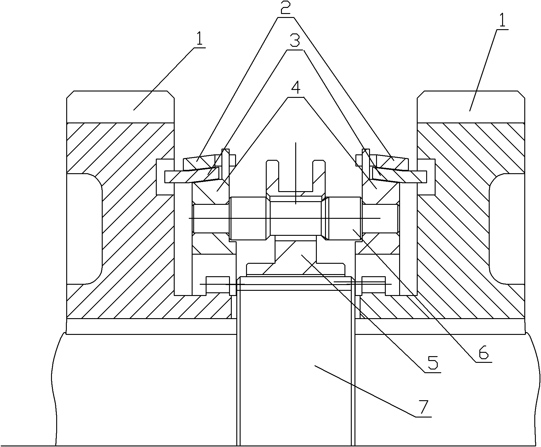
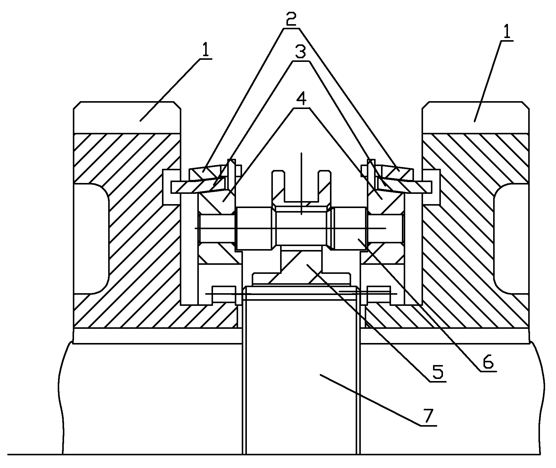
[0008] Such as figure 1 As shown, the double-cone lock-pin synchronizer is mainly composed of an outer cone 2, an intermediate ring 3, an inner cone 4, a gear sleeve 5, a lock pin 6, and a gear 1, wherein the gear sleeve 5 can be freely mounted on the lock pin 6 Sliding, the inner cone 4 is riveted with the lock pin 6, the intermediate ring 3 is floatingly connected with the gear 1 through the protrusion, the outer cone 2 is directly hung on the intermediate ring 3, and is connected with the inner cone 4 through the end claw. In this way, when the transmission is in motion, the tooth sleeve 5 is driven by the tooth seat to rotate with the two shafts, and at the same time the gear sleeve 5 drives the inner cone 4 and the outer cone 2 to rotate together with the two shafts of the transmission, and the intermediate ring 3 rotates with the gear 1. When the transmission changes When the gear is in gear, a relative angular velocity difference is generated between the second shaft of...


PUM


Abstract

The invention belongs to an automobile speed changer and particularly relates to a locking pin type double-cone synchronizer which is characterized by comprising an outer cone, an intermediate ring, an inner cone, a locking pin, a toothed sleeve and a gear, wherein the locking pin passes through a positioning pin hole on the toothed sleeve, thus the toothed sleeve can freely slide on the locking pin; the inner cone is riveted and fixed with the locking pin; the intermediate ring is in floating connection with the gear through a lug; the outer cone is directly hung on the intermediate ring; and the outer cone is connected with the inner cone through an end surface claw. When the gear of the speed changer provided by the invention is shifted, a relative angular speed difference is generated between the two shafts and gear of the speed changer; meantime, the toothed sleeve of the synchronizer pushes the locking pin, the locking pin pushes the inner cone, and the intermediate ring and the outer cone are sequentially pushed; and the synchronous friction torque of the axial thrust applied to the toothed sleeve of the synchronizer, which is generated on a friction cone surface, is equal to the sum of the friction torque between two pairs of cone surfaces, thereby reducing the gear shifting force of the synchronizer.

Description

technical field [0001] The invention belongs to the category of automobile transmissions, in particular to a lock-pin type double-cone synchronizer. Background technique [0002] At present, synchronizers are widely used in the gear shifting process of mechanical gear transmissions. Most of the synchronizers used in existing transmissions are inertial locking synchronizers. Although their structures are different, their working principles are the same, that is, the speed of the rotating parts to be meshed is adjusted before synchronization. The moment of inertia generated by their relative angular acceleration (or deceleration) speed is used to prevent their asynchronous meshing, and at the same time, it is also necessary to ensure that the rotational speeds of the rotating parts to be combined can be meshed after reaching synchronization. At present, the inertia locking synchronizer is mainly divided into pin-type synchronizer and lock-ring type synchronizer. Among them, t...

Claims


Application Information

Patent Timeline
Patent Type & Authority Applications(China)
IPC IPC(8): F16H57/00
Inventor 楼江天乔湘鹤徐孝华
Owner ZHEJIANG WANGLIYANG TRANMISSION CO LTD
Learn More