Shifting device for a motor vehicle transmission

A technology for vehicles and shifting devices, which is applied in the directions of transmissions, transmission parts, transmission control, etc., can solve problems such as high power loss, and achieve the effect of increasing torque transmission capacity

Active Publication Date: 2020-07-17
HOERBIGER ANTRIEBSTECHN HLDG
View PDF8 Cites 0 Cited by
  • Summary
  • Abstract
  • Description
  • Claims
  • Application Information

AI Technical Summary

Problems solved by technology

[0005] However, especially at high transmission rotational speeds, it has been found that the drag torque does not drop to the expected extent but still leads to undesirably large power losses in the motor vehicle transmission

Method used


Image

  • Shifting device for a motor vehicle transmission
  • Shifting device for a motor vehicle transmission
  • Shifting device for a motor vehicle transmission

Examples


Embodiment Construction

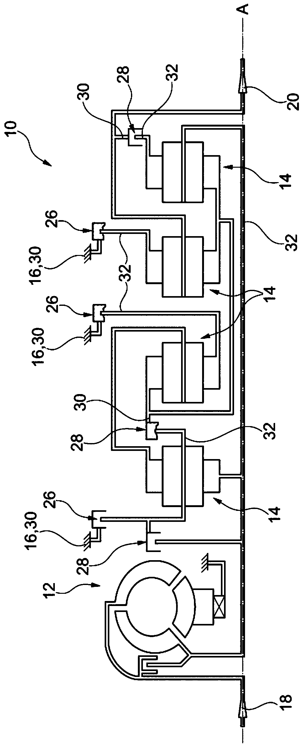
[0049] figure 1 An electro-hydraulic actuated, fully automatic stepped transmission 10 of a motor vehicle is shown, which includes a torque converter 12, four planetary transmissions or planetary gear sets 14, and a transmission housing 16 shown schematically. In addition, a drive shaft 18, a driven shaft 20 and a plurality of transmission shafts are also provided, and the planet carrier is also referred to as a transmission shaft in the following content. The transmission shafts are allocated to the respective planetary gear sets 14 and are arranged coaxially with each other.

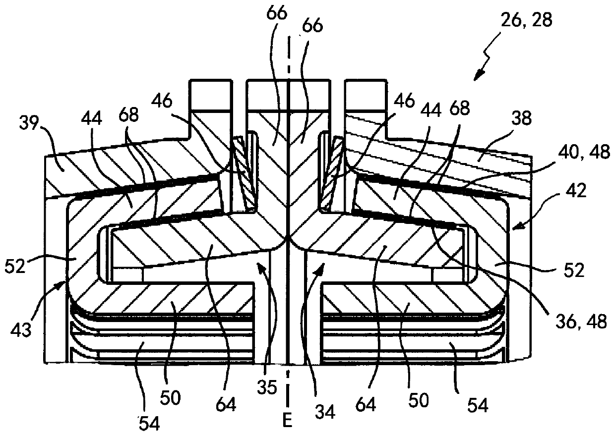
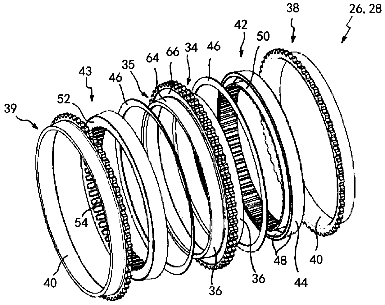
[0050] The stepped transmission 10 further includes shifting devices 26, 28, which can be applied to hydraulic pressure, and can couple the transmission shaft to another transmission shaft or the transmission housing 16, or connect the transmission shaft to the further transmission shaft Or the transmission housing 16 is separated.

[0051] The shifting device 26 that couples the transmission shaft to the ...


PUM


Abstract

A shifting device for a motor vehicle transmission has a first coupling component, a second coupling component rotatable about a transmission axis (A), an inner friction ring which has a conical surface on a radially outer face, an outer friction ring which has a conical surface on a radially inner face, and an intermediate friction ring having a C-shaped ring cross section, including a friction cone connected to the second coupling component for joint rotation with and for axial displacement with respect to the second coupling component, while the inner friction ring and the outer friction ring are connected to the first coupling component for joint rotation with and for axial displacement with respect to the first coupling component. The friction cone extends between the conical surfaces of the inner friction ring and outer friction ring.

Description

Technical field [0001] The present invention relates to a gear shifting device used for a motor vehicle transmission, especially for a fully automatic stepped transmission, which comprises: a first coupling part; a second coupling part, which can rotate around a transmission axis; an inner friction ring, which is in diameter The outer surface has a tapered surface and is connected to the first coupling part to rotate in conjunction with the first coupling part and move axially relative to the first coupling part; the outer friction ring has a cone on the radially inner surface Shaped surface, and connected to the first coupling part to rotate in conjunction with the first coupling part and move axially relative to the first coupling part; and an intermediate friction ring, which includes a friction cone and is connected to the second coupling part to Rotates in conjunction with the second coupling part and moves axially relative to the second coupling part. The friction cone ext...

Claims


Application Information

Patent Timeline
Patent Type & Authority Patents(China)
IPC IPC(8): F16D23/06F16H59/02
CPCF16D23/06F16H59/02F16D13/32F16D23/04F16D25/0632F16D2023/0681F16D2023/0693F16D2300/0214F16H3/66F16H57/0432F16H57/0473F16H63/30F16H63/3026F16H2063/3093F16H2200/0065F16H2200/2012F16H2200/2046F16H2200/2064F16H2200/2094F16D13/34F16D2300/06F16H61/0403
Inventor 尤尔根·宾德尔萨米·厄兹克安彼得·埃科特勒安德列亚斯·登普夫勒菲利普·明克维茨托拜厄斯·舒勒克里斯多夫·特劳特
Owner HOERBIGER ANTRIEBSTECHN HLDG
Why Eureka
Try Eureka