Method for acquiring element image based on stereo matching in panoramic imaging system

A technology of elemental image and panoramic imaging, which is applied in the direction of stereo system, image communication, electrical components, etc., can solve the problem of cross-interference of elemental image

Inactive Publication Date: 2012-10-03
CHANGCHUN UNIV OF SCI & TECH
View PDF0 Cites 0 Cited by
  • Summary
  • Abstract
  • Description
  • Claims
  • Application Information

AI Technical Summary

Problems solved by technology

[0005] The present invention proposes an elemental image acquisition method based on stereo matching in a panoramic imaging system to solve the problem of cross interference between elemental images collected in a traditional panoramic imaging system

Method used


Image

  • Method for acquiring element image based on stereo matching in panoramic imaging system
  • Method for acquiring element image based on stereo matching in panoramic imaging system
  • Method for acquiring element image based on stereo matching in panoramic imaging system

Examples


Embodiment Construction

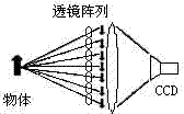
[0037] (1) In the panoramic imaging system, a high-resolution CCD camera is used as the acquisition device for space scene images, and the An array of CCD cameras is placed in the same plane, and the distance B between the lens centers of every two horizontally or vertically adjacent cameras is obtained. high-resolution images from different viewpoints;

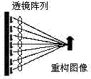
[0038] (2) According to the optical parameters of the display device in the panoramic system, the optical parameters include: the display microlens array is The microlenses are arranged in a square, and the focal length of the lenses is , the lens width is ,Will Convert a multi-viewpoint image into a 2D elemental image set suitable for displaying a microlens array. The conversion process is as follows:

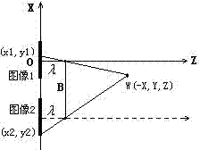
[0039] (1) Perform area-based stereo matching on two adjacent views, and calculate the depth and world coordinates of the object point according to the disparity of the matched pixel point pairs in the two adjacent im...


PUM


Abstract

The invention relates to a method for acquiring an element image based on stereo matching in a panoramic imaging system and belongs to the field of stereo display. The method comprises the following steps: using a CCD (charge coupled device) camera array as a mode for the panoramic imaging system to acquire a space image, and converting a plurality of acquired different viewpoint images into a 2D(two-dimensional) element image set used for the displaying of the panoramic imaging system based on the stereo matching principle, wherein the image set has a mode as same as the mode of the image acquired by using the traditional acquiring device, namely a micro-lens array, in the panoramic imaging system, thereby being compatible with the common display device of the panoramic imaging system and completely eliminating the cross interference which occurs when the micro-lens array in the panoramic imaging system is used for acquiring three-dimensional scene images.

Description

technical field [0001] The invention belongs to the field of stereoscopic display. Background technique [0002] Panoramic imaging integral imaging technology is an image technology that records and displays 3D spatial scene information through a microlens array. Figure 1 shows the collection and display parts of an existing panoramic imaging system. [0003] As shown in Figure 1(a), the acquisition part includes a microlens array and acquisition equipment such as a CCD camera. The 3D object space scene is captured by the CCD camera through the microlens array; each microlens records a part of the object space from different directions, corresponding to The small images generated are called element images, and there are as many corresponding element images as there are microlenses, so the 3D information of the space scene collected by the CCD camera is a series of 2D element image collections. In the display part, the 2D element image collection is placed behind the displa...

Claims


Application Information

Patent Timeline
Patent Type & Authority Patents(China)
IPC IPC(8): H04N13/00G03B37/00
Inventor 朴燕王宇
Owner CHANGCHUN UNIV OF SCI & TECH
Why Eureka
Try Eureka