
Eureka
For R&D, Eureka makes reading and utilizing patents & technical documents easy.
Eureka AIR
Designed for self-driven R&D workflows. Generate viable solutions, solve complex R&D challenges, empower your innovation with AI.

Eureka Materials
Designed for material experts only. Revolutionize your material R&D, from search, analyze, to developing new materials.

TechResearch
Generate reliable direction feasibility study reports for your R&D in just a few steps.

TechSeek
Discover and master advanced knowledge NOW. Basics, ideas, possibilities, all at once.

TechMind
As an expert in R&D Theories, TechMind can generates customized viable solutions instantly.

TechRisk
Analyze your overall solution with one click, know your potential R&D risks in advance.

TechMonitor
Get weekly tech updates, stay abreast of the latest tech innovations and key insights.
Centering device and centering method
A centering device and eccentric technology, applied in positioning devices, measuring devices, clamping, etc., to save space, improve durability, and achieve the effect of correcting accuracy
- Summary
- Abstract
- Description
- Claims
- Application Information
AI Technical Summary
Problems solved by technology
Method used
Image

Examples
Embodiment Construction
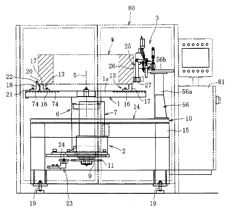
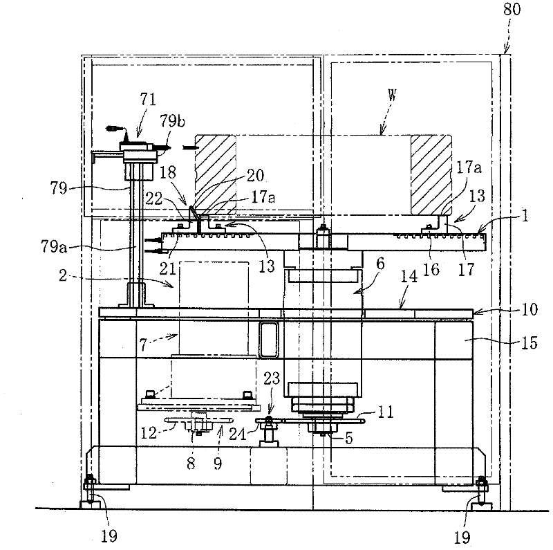
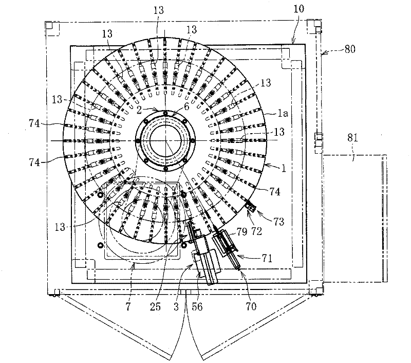
[0043] based on the following Figure 1 to Figure 16 Embodiments of the present invention will be described.
[0044] Figure 1 ~ Figure 3 The centering device of the present invention is shown. The centering device includes: a rotary table 1 on which a workpiece W is placed; a drive unit 2 for rotating the rotary table 1 around its axis; Inner ring or outer ring, etc.) The impact force imparting structure 3 that imparts impact force.
[0045] The drive unit 2 includes: a bearing structure 6 that supports the center shaft 5 of the turntable 1 so as to be rotatable about its axis, a drive motor 7 , an output shaft 8 of the drive motor 7 and the center shaft 5 Linkage members 9 linked together. The interlocking member 9 includes: a sprocket 11 mounted on the central shaft 5 of the turntable 1; a sprocket 12 mounted on the output shaft 8 of the driving motor 7; and a chain wound around the sprockets 11, 12. (Illustration omitted). The bearing structure 6 and the driving moto...
PUM
 Abstract
Description
Claims
Application Information
 - R&D Engineer
- R&D Manager
- IP Professional
- Industry Leading Data Capabilities
- Powerful AI technology
- Patent DNA Extraction
Browse by: Latest US Patents, China's latest patents, Technical Efficacy Thesaurus, Application Domain, Technology Topic, Popular Technical Reports.
© 2024 PatSnap. All rights reserved.Legal|Privacy policy|Modern Slavery Act Transparency Statement|Sitemap|About US| Contact US: help@patsnap.com