

Steering device
A steering device and steering column technology, applied in transportation and packaging, pedestrian/passenger safety arrangements, vehicle safety arrangements, etc., can solve the problems of high cost and rising cost of airbag devices, achieve low cost, suppress manufacturing costs, and improve The effect of impact energy
- Summary
- Abstract
- Description
- Claims
- Application Information
AI Technical Summary
Problems solved by technology
Method used
Image

Examples
Embodiment Construction
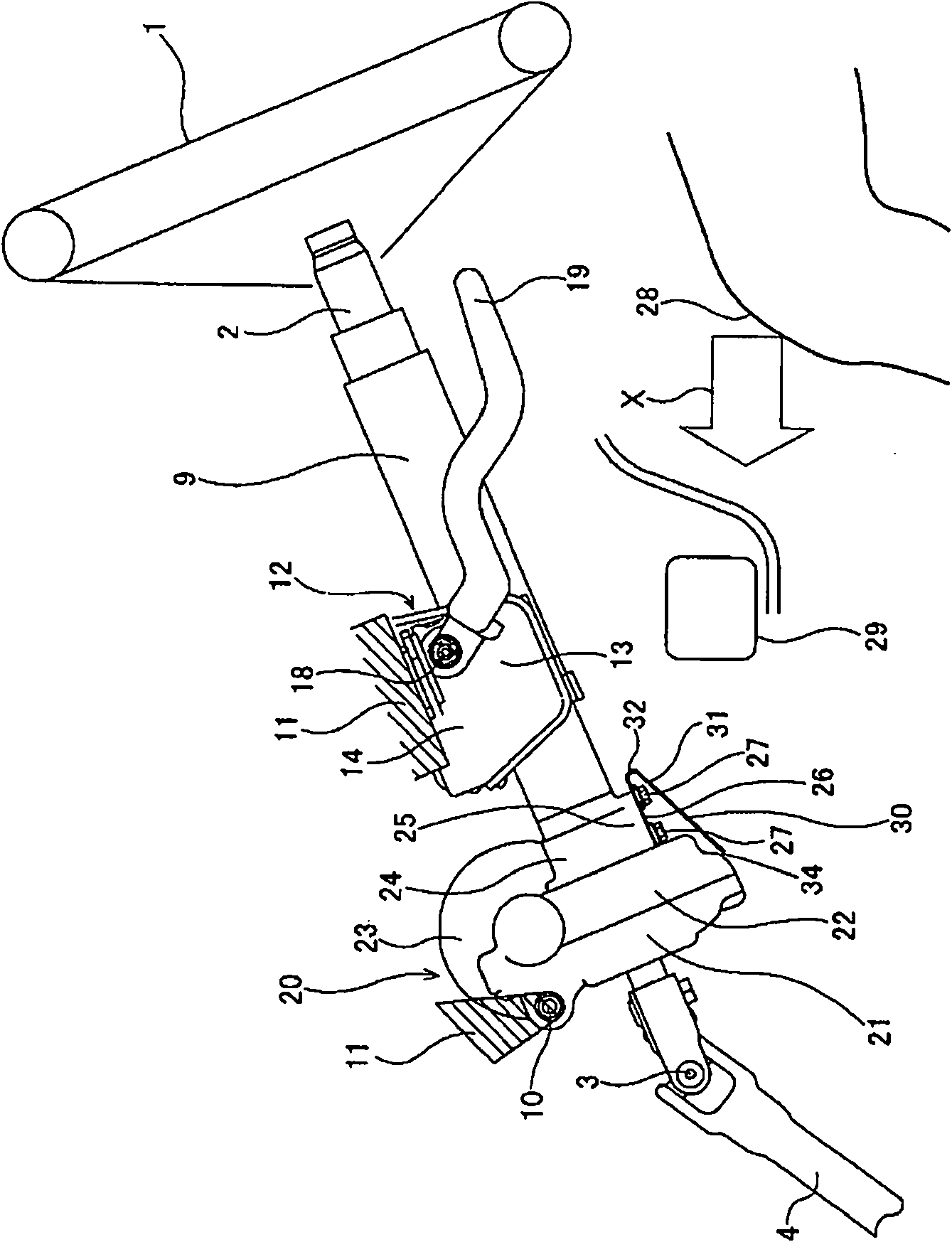
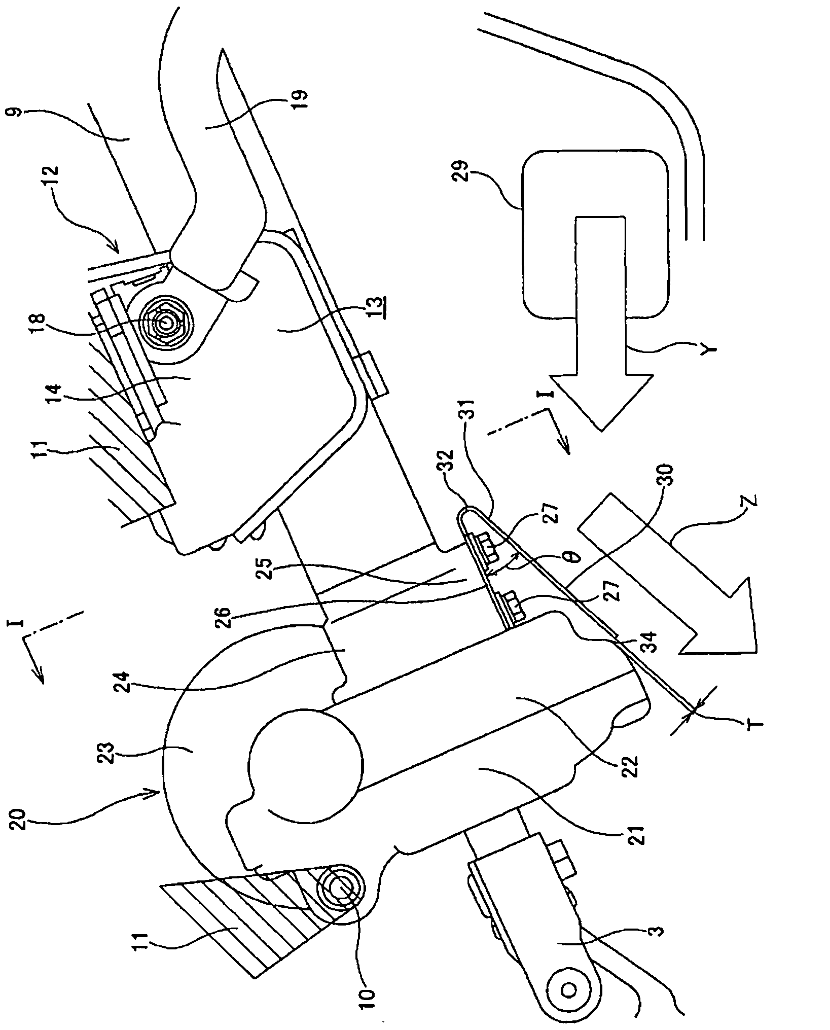
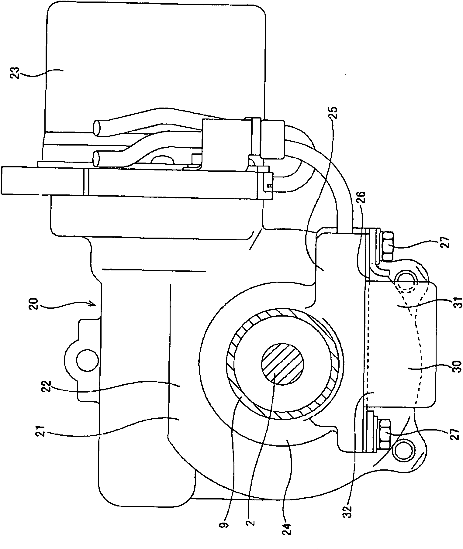
[0043] Figure 1 ~ Figure 3 A first example of an embodiment in which the present invention is applied to a column-type electric power steering device is shown. In addition, this example is characterized by the structure in which the coupling member fixed to the front end of the steering column 9 , that is, the lower end peripheral portion of the housing 21 constituting the electric power assist mechanism 20 . The structure and function of other parts are the same as the above Figure 10 ~ Figure 13 The conventional structures shown are the same, therefore, the same symbols are repeated for the same parts and are shown in the illustrations, and the description thereof is omitted or simplified, and the following description will focus on the characteristic parts of this example.
[0044] On the rear and lower portion of the lower end portion of the housing 21 (the rear portion when viewed from the front), which protrudes downward from the lower surface of the front end portion...
PUM
 Abstract
Description
Claims
Application Information