Improved drum and drum hub for a heat exchange brake, particularly for an automobile, and thus-fitted vehicle

A motor vehicle and brake drum technology, applied in the field of vehicles, can solve the problems of poor rigidity, quality and cooling effect, and achieve the effects of reducing quality, balancing processing enhancement, increasing rigidity and heat exchange

Active Publication Date: 2011-08-24
RENAULT SA
View PDF5 Cites 6 Cited by
  • Summary
  • Abstract
  • Description
  • Claims
  • Application Information

AI Technical Summary

Problems solved by technology

However, the rigidity, mass and cool

Method used


Image

  • Improved drum and drum hub for a heat exchange brake, particularly for an automobile, and thus-fitted vehicle
  • Improved drum and drum hub for a heat exchange brake, particularly for an automobile, and thus-fitted vehicle
  • Improved drum and drum hub for a heat exchange brake, particularly for an automobile, and thus-fitted vehicle

Examples


Embodiment Construction

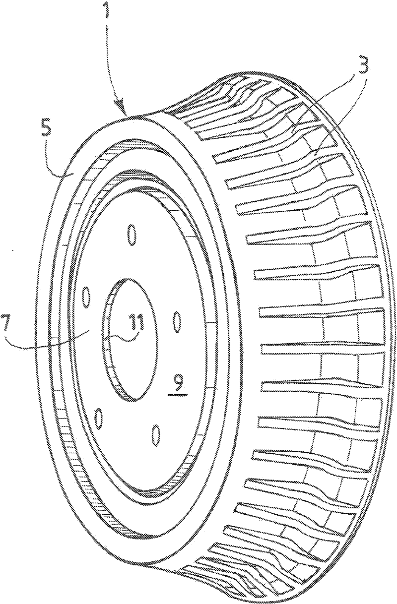
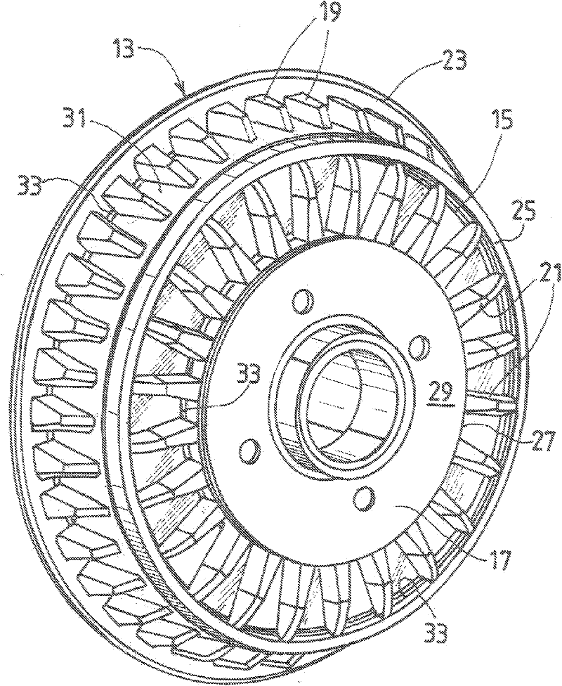
[0022] In FIG. 1 , a known brake drum hub 1 with peripheral ribs 3 is shown. The drum part 5 in the strict sense is incorporated into the hub part 7 of the vehicle and the entire assembly or drum hub 1 is constructed as an axially symmetrical single component. The drum part 5 has a cylindrical detent track (not shown) and an outer peripheral rib 3 extending across its width on the outer periphery opposite the detent track. The hub part 7 is coaxial with the drum part 5 and comprises a disc 9 which receives the axle (not shown) through its central circular opening 11 . In addition to the fact that they increase the rigidity of the drum part 5, the peripheral ribs 3 also contribute to the dissipation of the thermal energy generated during braking of the drum part. However, this energy dissipation can be achieved by, for example, figure 2 The illustrated drum hub 13 according to the invention is reinforced.

[0023] As shown in FIG. 1 , the drum part 15 is incorporated into th...


PUM


Abstract

The invention relates to an automobile wheel brake drum (15) including a cylindrical braking track coupled with a circular wall perpendicular to the rotational axis of the drum, one of the surfaces of said wall including so-called facial ribs (21) distributed about said rotational axis.

Description

technical field [0001] The present invention relates to a brake drum and drum hub with improved heat exchange, especially for motor vehicles, and a vehicle so equipped. Background technique [0002] Drum brakes are less efficient than disc brakes but are also less expensive to manufacture. [0003] However, drums are less resistant to overheating from braking than disc brakes. [0004] In order to overcome this drawback, some brake drums include, on the cylindrical wall of the drum on the surface facing the braking track, vanes extending along the generatrix to serve as cooling of the drum and dissipation of the heat generated during braking peripheral ribs. However, the performance of the rigidity, mass and cooling effect of this drum is poor. Contents of the invention [0005] The object of the invention is to improve known brake drums and to improve the drum braking performance of vehicles. [0006] In particular, according to the invention, a brake drum for a wheel...

Claims


Application Information

Patent Timeline
IPC IPC(8): F16D65/10
CPCF16D2065/1332F16D65/10
Inventor Y·盖伊J·卡米
Owner RENAULT SA
Why Eureka
Try Eureka