
Wet magnetic separator groove body

A technology for wet magnetic separators and tanks, applied in the field of magnetic separators, can solve problems such as tailings pipe blockage, poor separation indicators, and magnetic separators that cannot work normally and sort liquid levels, so as to improve the capture probability and prevent The effect of slurry sedimentation

Inactive Publication Date: 2011-08-31
BEIJING GENERAL RES INST OF MINING & METALLURGY +1
View PDF7 Cites 4 Cited by
  • Summary
  • Abstract
  • Description
  • Claims
  • Application Information

AI Technical Summary

Problems solved by technology

[0003] Because the height of the tailings pipe and the separation liquid level of the conventional magnetic separator is uncontrollable, and it is inevitable that the tailings pipe will be blocked on site, causing the magnetic separator to fail to work normally or the separation liquid level to be low, resulting in the separation index poor result

Method used


Image

  • Wet magnetic separator groove body
  • Wet magnetic separator groove body
  • Wet magnetic separator groove body

Examples


Embodiment Construction

[0028] The specific implementation manners of the present invention will be further described in detail below in conjunction with the accompanying drawings and embodiments. The following examples are used to illustrate the present invention, but are not intended to limit the scope of the present invention.

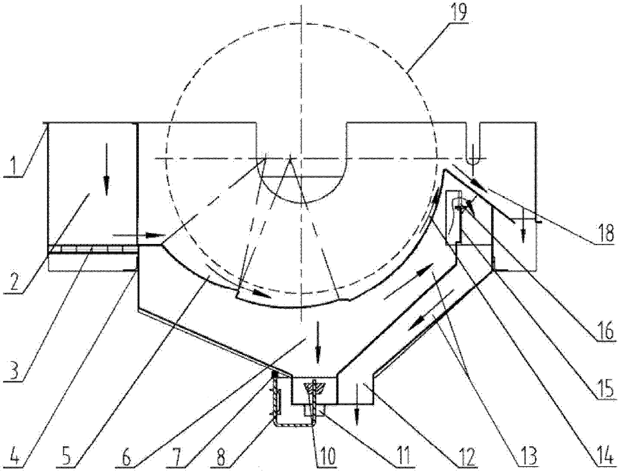
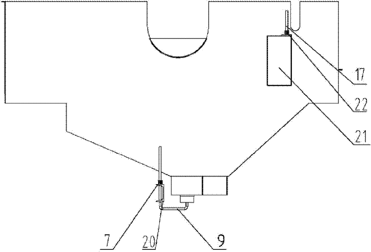
[0029] to combine figure 1 and figure 2 , figure 1 It is a schematic diagram of the internal structure of the wet magnetic separator tank body of the embodiment of the present invention; figure 2 It is a schematic diagram of the external structure of the tank body of the wet magnetic separator according to the embodiment of the present invention. like figure 1 and figure 2 As shown, a tank body 1 of a wet magnetic separator includes: an ore feeding space 2, a sorting space 5, a tailings discharge space and a concentrate conveying space 14, the ore feeding space 2 is connected to the sorting space 5, The upper part of the sorting space 5 is connected to the concent...


PUM


Abstract

The invention relates to the technical field of magnetic separators, in particular to a wet magnetic separator groove body (1). The wet magnetic separator groove body comprises an ore feeding space (2), a separation space (5), a tailing discharging space, a concentrate conveying space (14) and a liquid level adjusting mechanism (16), wherein the liquid level adjusting mechanism (16) is used for adjusting the ore pulp liquid level height in the groove body (1). The wet magnetic separator groove body (1) with the liquid level adjusting mechanism (16) has the characteristics of adaptability to higher fluctuation of an ore feeding amount and adjustable ore pulp liquid level height in the groove body; the matching relation between the height of the separation liquid level and the ore feeding amount is the best. At the same time, the invention also provides the ore feeding space (2) with a pre-magnet (3) and the separation space (5) with a step groove body structure. The magnetic ore catching probability can be effectively improved; ore pulp is prevented from precipitating; and crude ores do not sink into the groove to block the groove at the same time, so that the best working condition is achieved.

Description

technical field [0001] The invention relates to the technical field of magnetic separators, in particular to a tank body of a wet magnetic separator. Background technique [0002] The tank body of the magnetic separator is an important component of the magnetic separator to achieve separation. The tank body is usually composed of a feeding area, a sorting area, an unloading area, a tailings pipe and an overflow area. In order to ensure the normal operation of the magnetic separator, when the feeding area and the sorting area are unobstructed, the sorting liquid level must be ensured, that is, there is ore pulp passing through the overflow area, so that the magnetic separator can obtain the best separation under normal operation. Select indicators. [0003] Because the height of the tailings pipe and the separation liquid level of the conventional magnetic separator is uncontrollable, and it is inevitable that the tailings pipe will be blocked on site, causing the magnetic s...

Claims


Application Information

Patent Timeline
Patent Type & Authority Applications(China)
IPC IPC(8): B03C1/10
Inventor 刘永振史佩伟赵瑞敏尚红亮
Owner BEIJING GENERAL RES INST OF MINING & METALLURGY
Learn More