Hydraulic low-speed walking transmission system

A transmission system and low-speed technology, applied in the field of transmission system, can solve the problems of damaged diesel engine and increased speed

Active Publication Date: 2011-08-31
GEMAC ENG MACHINERY
View PDF7 Cites 7 Cited by
  • Summary
  • Abstract
  • Description
  • Claims
  • Application Information

AI Technical Summary

Problems solved by technology

The energy obtained by the motor during the downhill or deceleration stage is transferred to the oil pump to do work on the diesel engine. The diesel engine absorbs the power in

Method used


Image

  • Hydraulic low-speed walking transmission system
  • Hydraulic low-speed walking transmission system
  • Hydraulic low-speed walking transmission system

Examples


Embodiment Construction

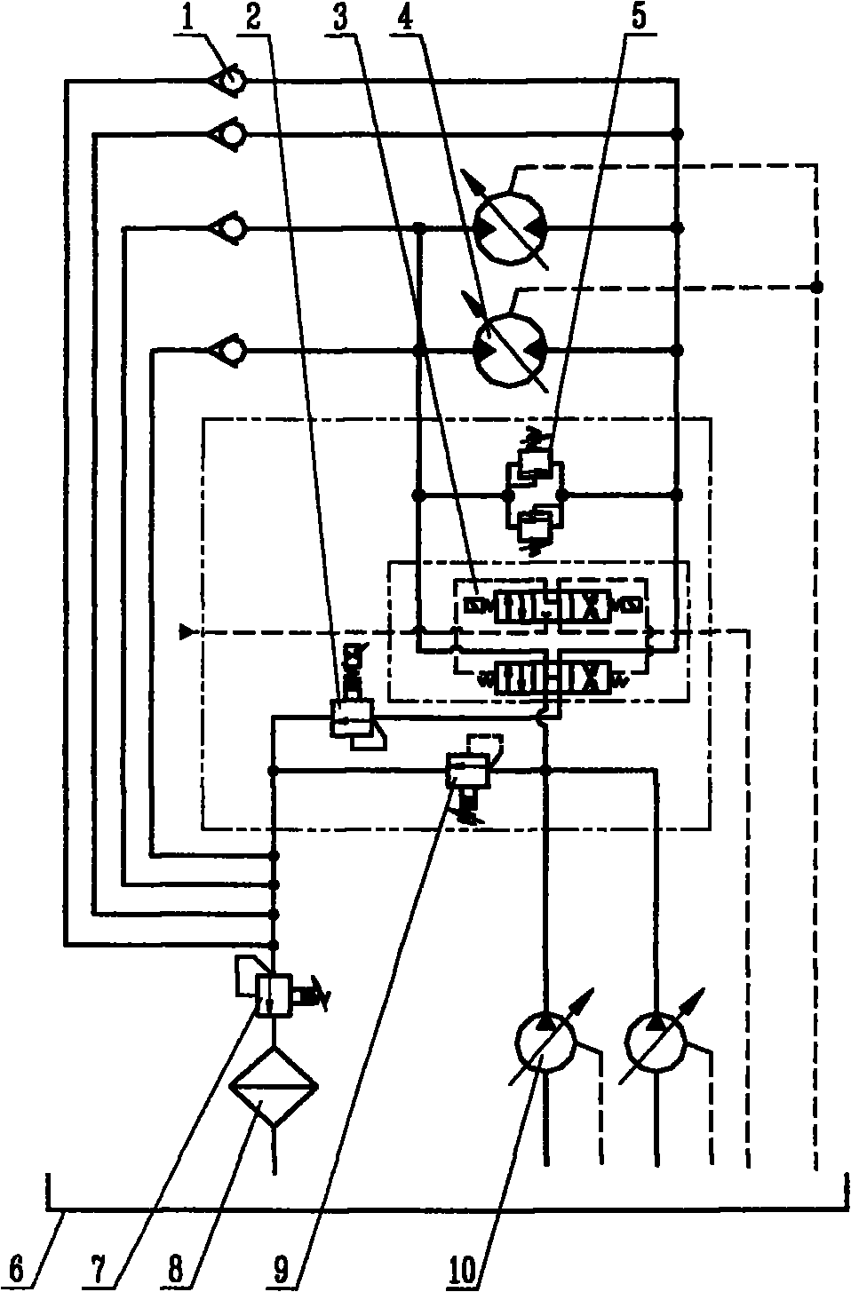
[0014] figure 1 Among them, hydraulic oil pump 10, pilot-operated second relief valve 9 (pilot-operated relief valve), electro-hydraulic reversing valve 3, electric proportional relief valve 2, check valve 1, The hydraulic motor 4, the cooling device 8, the oil tank 6, and the direct-acting third overflow valve 5 that can drive the vehicle to run under the action of pressure oil form an open hydraulic system circuit. The electro-hydraulic reversing valve 3 has two working oil ports, any one of which is used for the high-pressure working oil port, and the other is used for the low-pressure working oil port, the two oil ports of the hydraulic motor, the oil inlet and the electro-hydraulic reversing valve The high-pressure working oil port is connected, and the oil outlet is connected with the low-pressure working oil port of the electro-hydraulic reversing valve. After the two oil pumps 10 merge, they are connected to the inlet P of the electro-hydraulic reversing valve 3 throu...


PUM


Abstract

The invention discloses a hydraulic low-speed walking transmission system. The oil pump of the system is connected with the inlet of an electrohydraulic selector valve by a pipeline; the high pressure working oil port and the low pressure working oil port of the electrohydraulic selector valve are connected with the oil inlet and the oil outlet of a hydraulic motor; the oil returning port of the electrohydraulic selector valve is communicated with a hydraulic oil tank; and the hydraulic motor is in transmission connection with an axle gear box. In the walking process, the oil outlet of the hydraulic motor is always communicated with the low pressure working oil port of the electrohydraulic selector valve, and does not enter the oil inlet pipeline of an oil pump any more. In the descending process, the energy acquired by the hydraulic motor cannot be transferred to the oil pump and a diesel engine, so that the rotational speed of the diesel engine increases. An electric proportional overflow valve is arranged between the oil returning port of the electrohhydraulic selector valve and the hydraulic oil tank, and an oil returning pressure applied to the hydraulic motor is changed by adjusting the electric proportional overflow valve, so that the stress on a vehicle is balanced, and the constant-speed walking of the vehicle is ensured. Check valves are arranged between the oil inlet and the oil outlet of the hydraulic motor and the oil returning pipeline of the electric proportional overflow valve, so that the problem that suction easily occurs in the hydraulic motor in an open hydraulic system can be solved.

Description

technical field [0001] The invention relates to a hydraulic uniform low-speed running system of a railway rail grinding vehicle, in particular to a transmission system that uses an open hydraulic system to drive the vehicle to run. Background technique [0002] At present, the low-speed running of domestic and foreign railway rail vehicles adopts a hydraulic closed system to realize the running drive, and the direction of the oil circuit is from oil pump→hydraulic motor→oil pump, forming a closed circulation system. The disadvantage of adopting a closed system is that the speed of the vehicle will increase when the vehicle is running on a "growth" downhill, the oil pump will become the "motor" working condition, and the motor will become the "oil pump" working condition, and the high and low pressure ends of the pipeline will interact with each other. Change. Similarly, during the deceleration phase of the vehicle, the working conditions of the oil pump and the motor will a...

Claims


Application Information

Patent Timeline
IPC IPC(8): B61C9/14F15B11/02F15B13/02
Inventor 罗居正陈斌鄢加生舒小红
Owner GEMAC ENG MACHINERY
Why Eureka
Try Eureka