Light source device

A light source device and technology for accommodating parts, applied in the direction of light source, electric light source, lighting device, etc., can solve the problems of low efficiency, troublesome assembly, inconvenient application, etc., and achieve the effect of convenient application

Inactive Publication Date: 2011-08-31
SHANGHAI XIANGLONG ELECTRONICS TECH
View PDF3 Cites 2 Cited by
  • Summary
  • Abstract
  • Description
  • Claims
  • Application Information

AI Technical Summary

Problems solved by technology

After the production is completed, the orientation of the light outlet 122 of the lampshade 12 is fixed and cannot be changed, so that if the light source to be used in the application device has a light projection direction different from that of the traditional linear light source 1, the traditional linear light source 1 must be redesigned and replaced. Molding production, so the design structure of the traditional linear light source 1 is not very convenient in application
[0005] Moreover, most of the light guide rod 11 is covered by the lampshade 12, and only part of the light can be emitted from the light outlet 122, so the efficiency of light use is low.
Furthermore, the traditional linear light source 1 is not only complex in structure, but also cumbersome to assemble.

Method used


Image

  • Light source device
  • Light source device
  • Light source device

Examples


Embodiment Construction

[0020] Below in conjunction with accompanying drawing and specific embodiment the present invention is described in further detail:

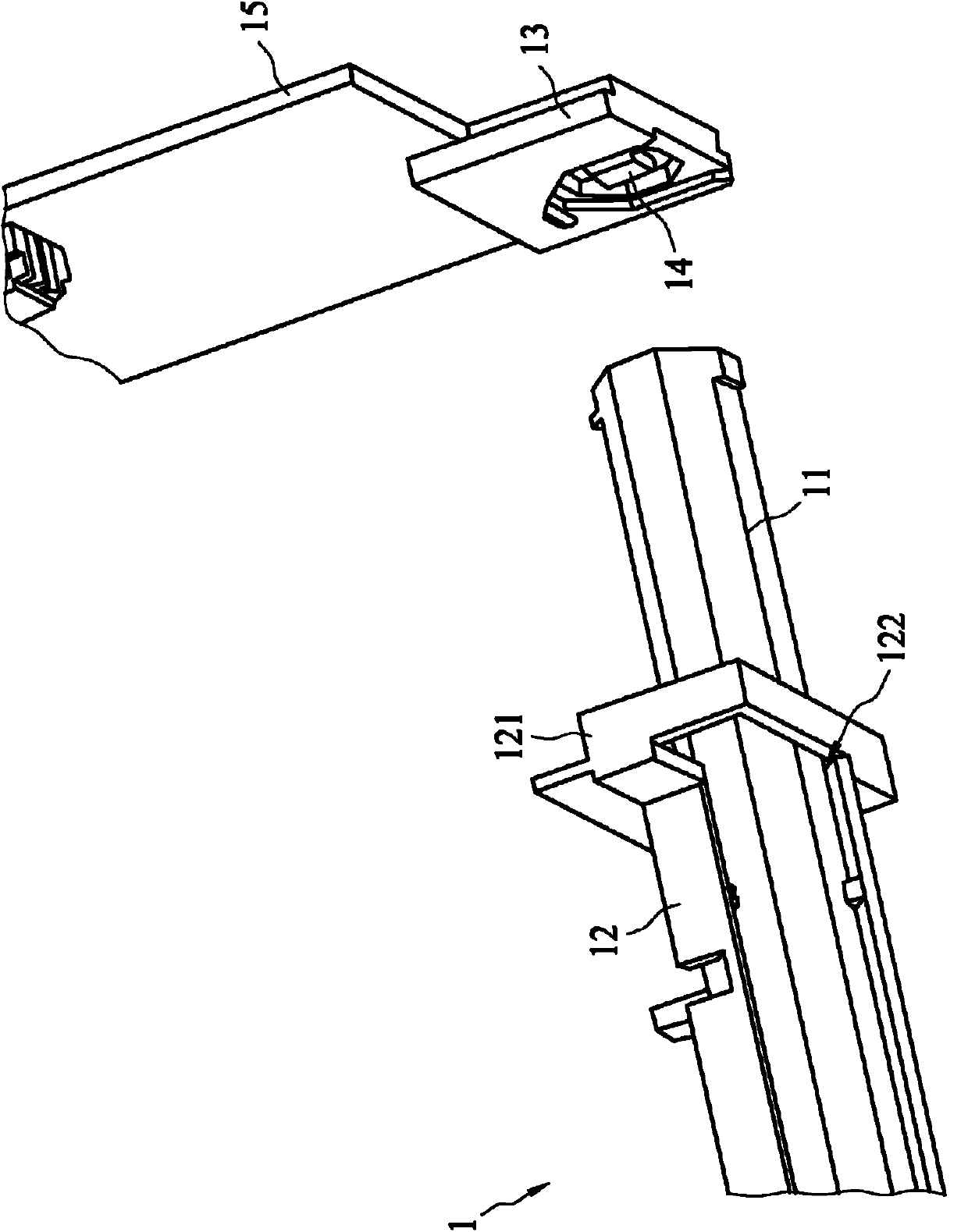
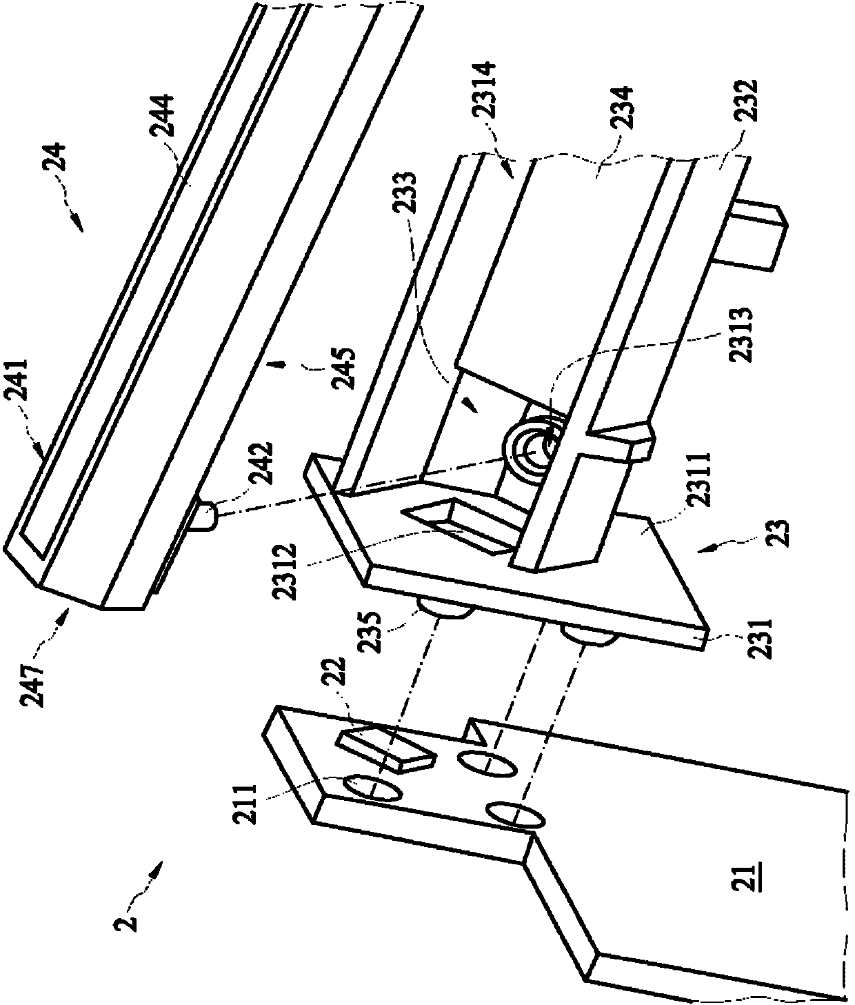
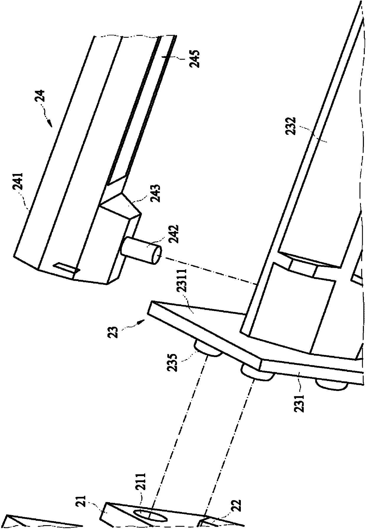
[0021] An embodiment of the present invention discloses a light source device, which includes a substrate, a light-emitting component, a first holder, and a light-guiding component. The light emitting component is arranged on the substrate. The first holder has a base and an accommodating part. The base has a surface and a through hole, and the through hole is formed on the surface. The accommodating portion protrudes from the surface of the base and at least partially surrounds the through hole of the base. The light guide component includes an end. The end portion is accommodated in the accommodating portion of the first holder, wherein the light-emitting component is located on an end face of the light-guiding component through the through hole.

[0022] Another embodiment of the present invention discloses a light source device, which in...


PUM


Abstract

The invention relates to a light source device which comprises a substrate, a light emitting component, a first holder and a light guide component, wherein the light emitting component is arranged on the substrate; the first holder is provided with a base and an accommodating part; the base is provided with a surface and a through hole; the through hole is formed on the surface; the accommodating part convexly extends out of the surface of the base; the accommodating part surrounds the through hole at least partially; the light guide component comprises an end; the end is accommodated in the accommodating part of the first holder; and the light emitting component is positioned at one tail end surface of the light guide component through the through hole. The light source device provided by the invention has the beneficial effect that the light emitting angle can be elastically adjusted, therefore, the light source device is more convenient to use.

Description

technical field [0001] The invention relates to a linear light source of a light source device, in particular to a linear light source device. Background technique [0002] An image scanning device is a tool that optically converts an image, document or object into a digital image. The image scanning device usually includes a line-shaped light source, which illuminates a part of the scanned object. The reflected light passes through an optical module and is divided into three lights: red, blue and green. Image sensors (such as charge-coupled devices) convert red, blue, and green light into analog signals. The analog signal is converted into a digital signal by an analog / digital converter, and then output. Traditionally, a linear light source can be composed of a light guide column, a cold cathode lamp or a light emitting diode. [0003] figure 1 A conventional linear light source 1 is illustrated as an example. refer to figure 1 As shown, the linear light source 1 inc...

Claims


Application Information

Patent Timeline
IPC IPC(8): F21S2/00F21V8/00F21V7/22F21V19/00F21K9/20F21Y115/10
Inventor 黄文彦
Owner SHANGHAI XIANGLONG ELECTRONICS TECH
Why Eureka
Try Eureka