Stereographic projection optical system

An optical system and stereo projection technology, applied in optics, optical components, instruments, etc., can solve the problems of many parts and complex structure, and achieve the effect of reducing parts, simple structure and reducing price

Inactive Publication Date: 2011-08-31
SHANGHAI LEXVU OPTO MICROELECTRONICS TECH
View PDF6 Cites 3 Cited by
  • Summary
  • Abstract
  • Description
  • Claims
  • Application Information

AI Technical Summary

Problems solved by technology

[0006] The problem solved by the present invention is that the stereoscopic projection optical system in the prior art uses many components and has a complex structure

Method used


Image

  • Stereographic projection optical system
  • Stereographic projection optical system
  • Stereographic projection optical system

Examples


Embodiment Construction

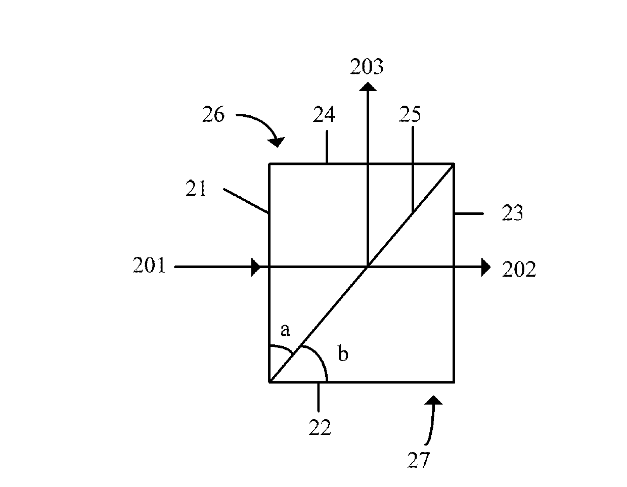
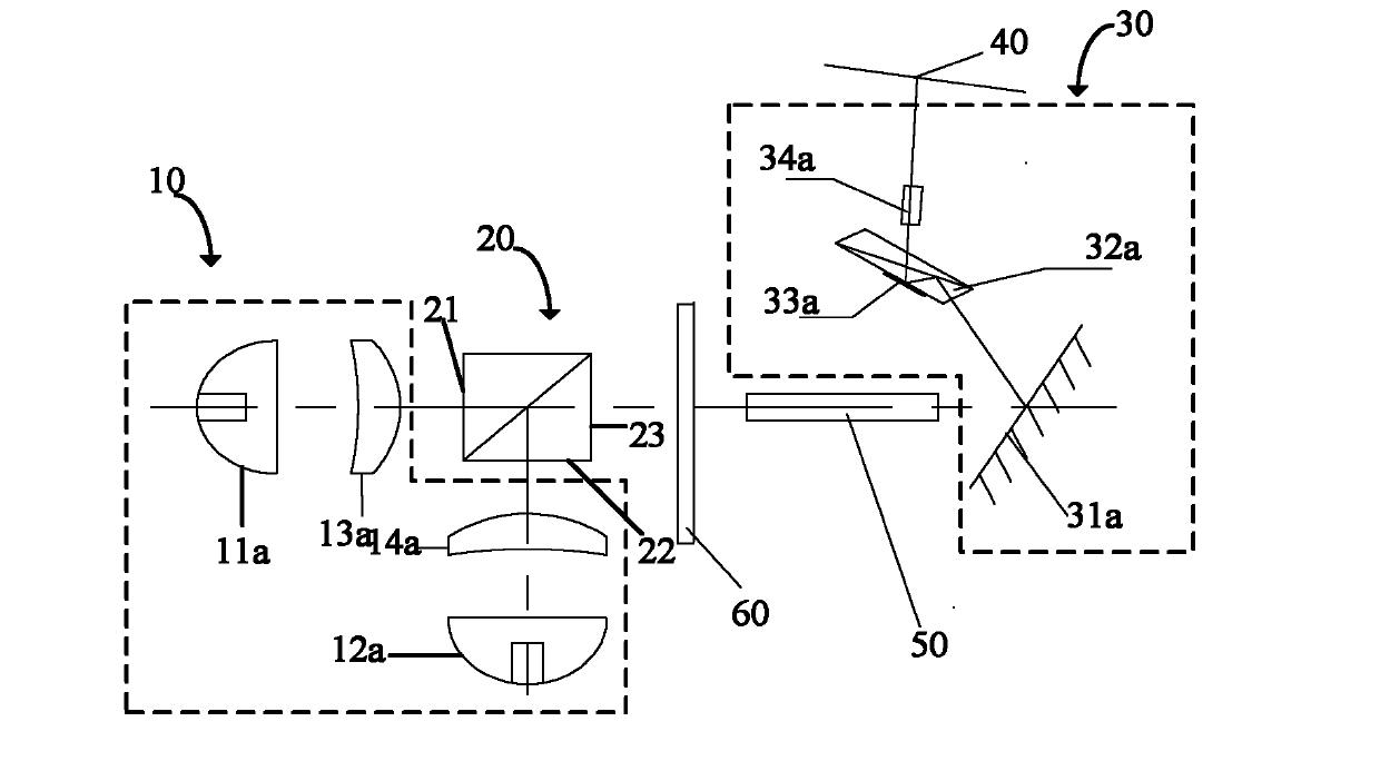
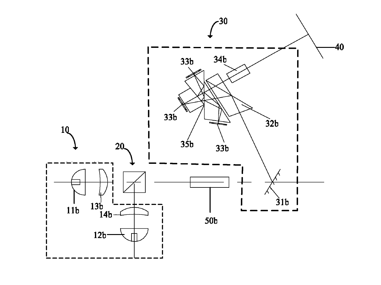
[0052] combined reference figure 2 , image 3 , Figure 4 , Figure 5 , the stereoscopic projection optical system of the specific embodiment of the present invention includes: a light emitting device 10 for emitting light; a polarization beam splitter 20 for receiving the light emitted by the light emitting device 10 and converting it into two beams whose polarization directions are perpendicular to each other The polarized light is emitted; the projection device 30 is configured to receive the polarized light emitted by the polarization splitting device and image the received polarized light.

[0053] In a specific embodiment of the present invention, the stereoscopic projection optical system further includes: a projection screen 40 located at a position where the projection device 30 converges received polarized light to form an image, and is used for displaying images.

[0054] figure 1 It is a structural schematic diagram of a polarization splitting device according...


PUM


Abstract

A stereographic projection optical system comprises a light-emitting device, which emits light; polarized light-splitting device, which receives the light emitted from the lighting-emitting device and converts the light to two beams of polarized light for emitting, with polarization directions of the two beams being perpendicular to each other; and a projection device which receives the polarized light emitted from the polarized light-splitting device and realizes imaging of the polarized light. The stereographic project optical system is simple in structure and convenient for installation.

Description

technical field [0001] The invention relates to the field of stereo imaging, in particular to a stereo projection optical system. Background technique [0002] Imaging technology continues to develop, with higher and higher pixels, and we are able to see clearer, brighter, and colorful videos and graphics on larger screens, but they always have a limitation, that is, they are two-dimensional. The real world seen by our eyes is not just a simple flat image, but a stereoscopic three-dimensional with depth of field. This ability to perceive three-dimensionality is a side function of retinal inconsistency (or a slight shift in the position of an object seen by the left and right eyes) . Therefore, if a stereoscopic projection device is to be designed, it must simulate the parallax of retinal imaging when humans watch objects. This sense implies that what we see is real (or almost real), rather than flat and two-dimensional. [0003] Stereo projection is realized through the p...

Claims


Application Information

Patent Timeline
IPC IPC(8): G02B27/26G02B27/18G03B21/20G03B21/14G02B30/25
Inventor 张镭赵瑞萍
Owner SHANGHAI LEXVU OPTO MICROELECTRONICS TECH
Why Eureka
Try Eureka