Relay connector

A technology for relay connectors and clamping parts, which is applied in the direction of connection, parts of connection devices, electrical components, etc., and can solve problems such as probe damage, inspection or inspection result deviations, etc.

Inactive Publication Date: 2011-08-31
YOKOWO CO LTD
View PDF6 Cites 1 Cited by
  • Summary
  • Abstract
  • Description
  • Claims
  • Application Information

AI Technical Summary

Problems solved by technology

However, when the inspection work is carried out in a hurry, the other side of the first clamping member and the second clamping member may be closed in a state where the flexible printed circuit board is not reliably inserted to the restricted position. Whether the needle contacts the terminal of the flexible printed circuit board or does not contact the appropriate position, the inspection may not be performed correctly or the inspection result may be biased.
Moreover, if the flexible printed circuit board is pulled out in a state where the other side of the first clamping member and the second clamping member are not reliably opened, the force in the bending direction acts on the probe, causing damage to the probe and Cause of wear

Method used


Image

  • Relay connector
  • Relay connector
  • Relay connector

Examples


Embodiment Construction

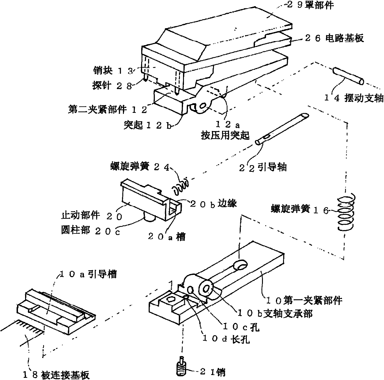
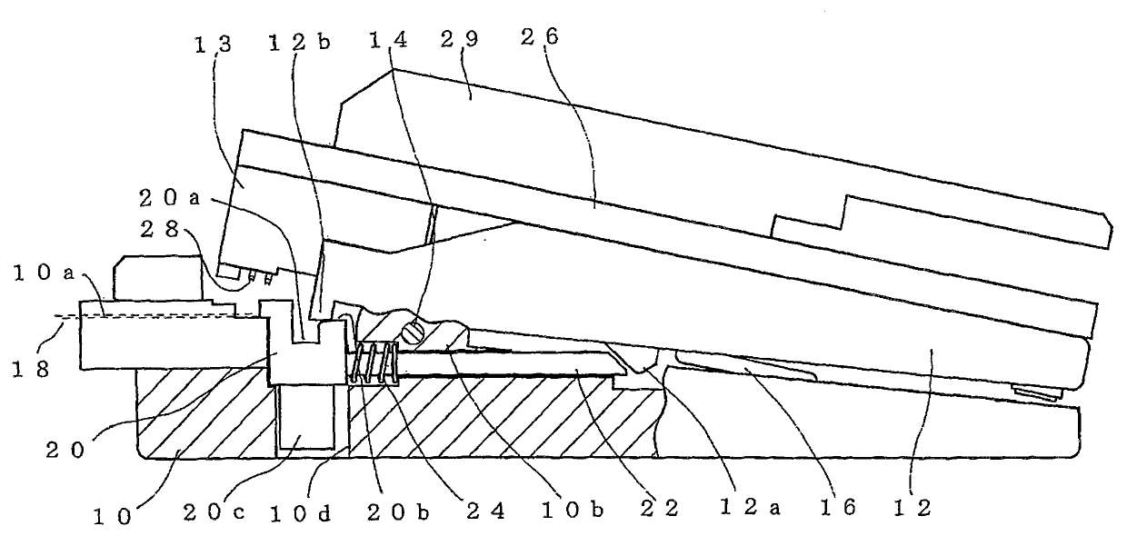
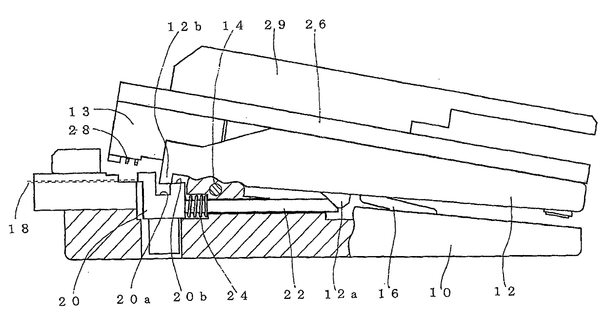
[0063] Below, refer to Figure 1 to Figure 6 , to illustrate the first embodiment of the present invention. figure 1 It is an exploded perspective view of the first embodiment of the relay connector of the present invention. figure 2 Yes figure 1 A partially cutaway side view of a state in which the other sides of the first clamping member and the second clamping member are opened in the assembled state of the relay connector shown. image 3 From figure 2 Partially cutaway side view of the state where the insertion of the substrate to be connected is started and the stopper member moves to the swing support shaft side. Figure 4 is shown inserted into the substrate to be connected from figure 2 change into image 3 Partial enlarged view of the state of each part in the state, the single dotted line shows figure 2 state, the solid line shows image 3 status. Figure 5 It is a partially cutaway side view of a state in which the protrusion is inserted into the groove of...


PUM


Abstract

The invention provides a relay connector. When a connected substrate is inserted in an appropriate position, the front sides of a first clamping component and a second clamping component are closed, and a probe can abut against the terminal of the connected substrate. In this case, first and the second clamping components can freely swing, and the front sides are closed through the elastic force application of a helical spring (16). The front side of the first clamping component is provided with a stop component in a manner of smooth reciprocating motion in a regulated range. An elastic force is applied to the front of the stop component through another helical spring (24). When being disposed in the front, the stop component abuts against the boss on the second clamping component to limit the front side closing, and removes the abutting when moving backwardly to close the front side. When the stop component moves backwardly by overcoming the elastic force of the helical spring (24) through the insertion of the connected substrate, the abutting of the boss can be removed. The probe on the second clamping component abuts against the terminal of the connected substrate.

Description

technical field [0001] The present invention relates to a relay connector used for electrically connecting a terminal arranged at an end of a substrate to be connected on the inspection side such as a flexible printed circuit connected to an electronic component, to a measuring device or the like. Background technique [0002] In small electronic devices such as mobile phones and digital cameras, the flexible printed circuit board is often electrically connected to the electronic circuit on which the electronic components are mounted, and the terminals arranged on the end of the flexible printed circuit board are connected via the connector. etc. to connect with other electronic circuits to assemble electronic equipment. The suitability of the individual electronic circuits is preferably checked before carrying out this assembly. For this reason, it is necessary to electrically connect the terminals provided on the ends of the flexible printed circuit board to an inspection...

Claims


Application Information

Patent Timeline
Patent Type & Authority Applications(China)
IPC IPC(8): H01R13/502H01R13/639H01R12/77
Inventor 平子了一
Owner YOKOWO CO LTD
Why Eureka
Try Eureka