Rolling body screw device

a screw device and rolling body technology, applied in mechanical equipment, gearing, hoisting equipment, etc., can solve the problems of high production cost, troublesome rolling body to be rolled, and variable dimension, so as to prevent the generation of gaps, increase the service life of the return pipe, and high load

Active Publication Date: 2008-12-09
THK CO LTD
View PDF13 Cites 1 Cited by
  • Summary
  • Abstract
  • Description
  • Claims
  • Application Information

AI Technical Summary

Benefits of technology

[0009]The present invention has been made in view of the above problem. It is an object of the present invention to provide a rolling body screw device, in which, in forming a return pipe through abutment of a pair of return pipe halves obtained through splitting along a non-load passage for the rolling bodies, the abutment of these return pipe halves is effected reliably, whereby generation of a gap between the abutment surfaces of the return pipe halves during circulation of the rolling bodies is prevented, making it possible to withstand a long-term use even under a condition of high load and large thrust.
[0010]To achieve the above object, in the rolling body screw device of the present invention, a return pipe is formed through combination of a pair of return pipe halves obtained by splitting along a non-load passage, and a pipe hold down member is fixed to a nut member so as to be astride the return pipe to thereby fix the return pipe to the nut member. Further, formed on each return pipe half is a flange portion protruding in a direction crossing the non-load passage, and formed on the pipe hold down member are an engagement portion equipped with a recess to be fit-engaged with the return pipe and a pair of fixing leg portions covering the flange portions of each of the return pipe halves, with fastening members being fastened to the nut member through the fixing leg portions of the pipe hold down member and the flange portions of the return pipe halves. When the fixing leg portions of the pipe hold down member are fixed to the nut member by the fastening members, the engagement portion of the pipe hold down member exerts a tightening effect such that the split faces of the pair of return pipe halves are biased to abut each other.
[0011]According to the present invention, constructed as described above, when the rolling bodies circulate in the non-load passage path provided inside the return pipe, even if a force attributable to the collision of the rolling bodies with the inner peripheral wall of the return pipe is exerted on the abutment surfaces of the pair of return pipe halves so as to push them open, it is possible to firmly maintain the abutment state of the return pipe halves by utilizing the tightening force of the pipe hold down member. As a result, it is possible to prevent generation of a gap between the pair of return pipe halves, making it possible to achieve an increase in the service life of the return pipe even when used under a condition of high load and large thrust.

Problems solved by technology

This, however, involves high production cost, and is subject to variation in dimension when performing the bending.
Thus, as the operation time of the rolling body screw device is accumulated, a gap is generated between the abutment surfaces of the return pipe halves, so that there is a fear of causing a trouble of the rolling bodies to be rolled out through this gap.
In particular, in the case of a rolling body screw device for higher load and larger thrust, the rolling bodies collide with the inner peripheral wall of the return pipe so much the more vigorously, so that the gap is likely to be generated at an early stage, which makes it necessary to reliably effect the abutment of the pair of return pipe halves against the impact force due to this collision.

Method used


Image

  • Rolling body screw device
  • Rolling body screw device
  • Rolling body screw device

Examples


Embodiment Construction

[0023]In the following, the rolling body screw device of the present invention will be described in detail with reference to the accompanying drawings.

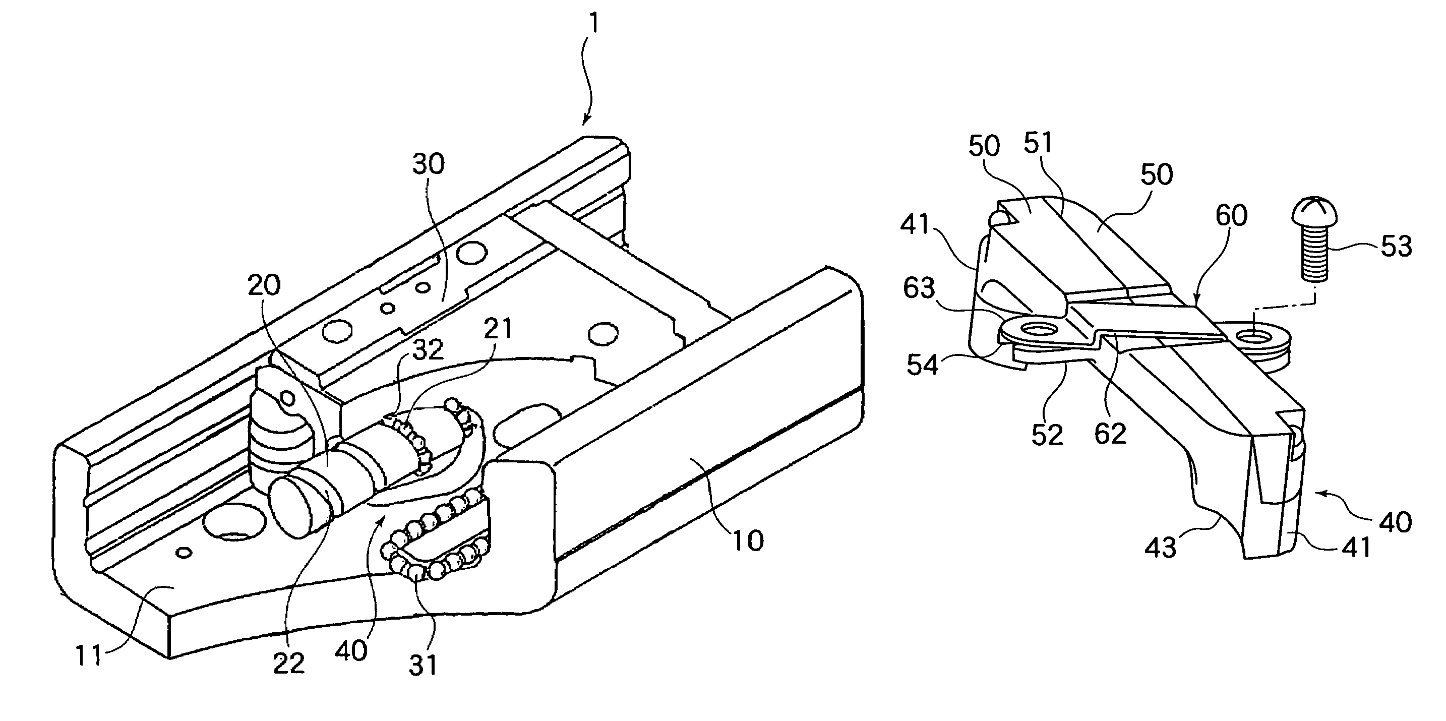
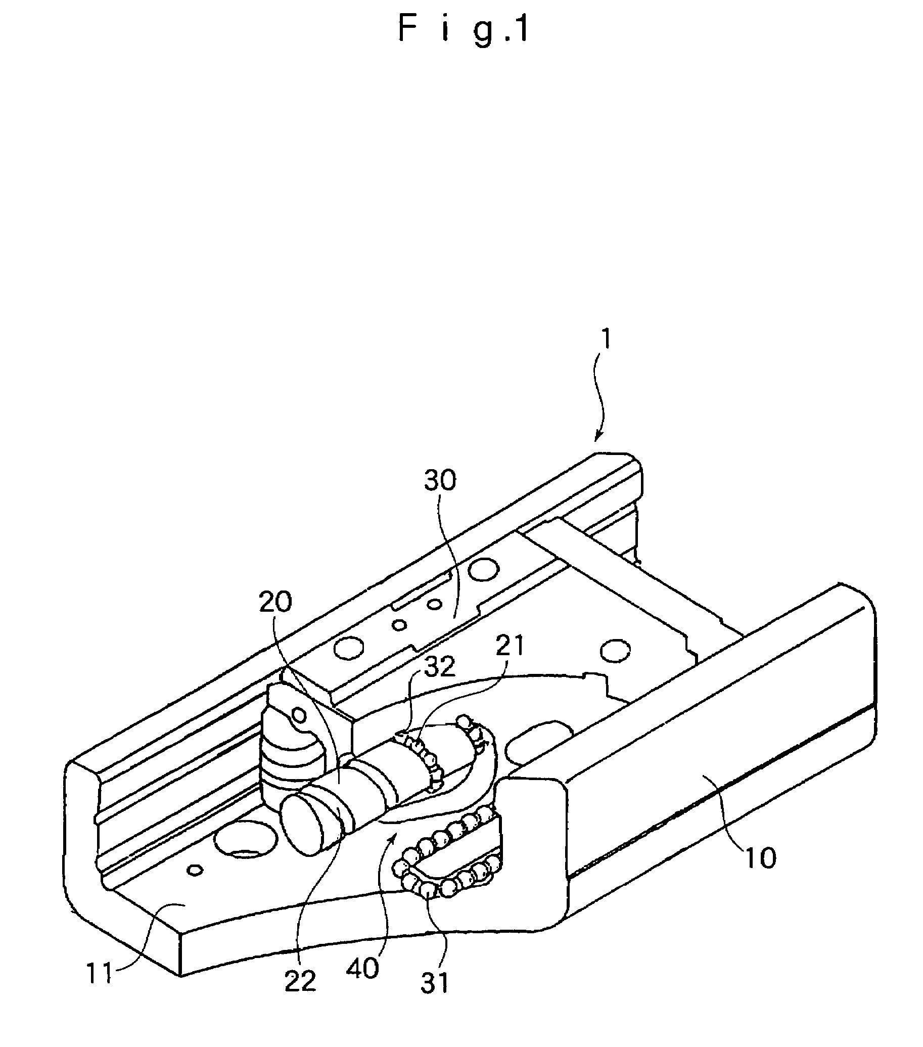
[0024]FIG. 1 shows a linear actuator 1 including a rolling body screw device to which the present invention is applied. The linear actuator 1 is composed of an outer rail 10 formed as a channel with a recessed groove 11, a screw shaft 20 rotatably provided in the recessed groove 11 of the outer rail 10, and an inner block 30 having a through-hole through which the screw shaft 20 is passed and arranged inside the recessed groove 11 of the outer rail 10.

[0025]The inner block 30 is mounted to the outer rail 10 through the intermediation of a plurality of balls 31, and the inner block 30 is equipped with an endless circulation path through which the balls 31 circulate. As a result, the inner block 30 can freely reciprocate inside the recessed groove 11 of the outer rail 10.

[0026]Further, inner block 30 is threadedly engaged with the screw...


PUM


Abstract

A return pipe is constituted by combining a pair of return pipe halves split along a non-load passage. A pipe hold down member is fixed to a nut member so as to be astride the return pipe, fixing the return pipe to the nut member. A flange portion is formed on each of the return pipe halves, while a pair of fixing leg portions covering the flange portion of each return pipe half is formed on the pipe hold down member. Fastening members pass through the fixing leg portions of the pipe hold down member and the flange portion of the return pipe halves and are fastened to the nut member. When the fixing leg portions of the pipe hold down member are fixed to the nut member by the fastening members, an engagement portion of the pipe hold down member is configured to tighten the pair of the return pipe halves in the direction where split faces of the return pipe halves abut against each other.

Description

TECHNICAL FIELD[0001]The present invention relates to a rolling body screw device in which a nut member is threadedly engaged with a screw shaft through the intermediation of rolling bodies such as balls or rollers, and which converts a rotary movement of a motor to a linear movement in, for example, a worktable of a machine tool, and more specifically, to a rolling body screw device in which a substantially U-shaped return pipe is attached to a nut member to form an endless circulation path for the rolling bodies.BACKGROUND ART[0002]There are known various types of rolling body screw device in which an endless circulation path for rolling bodies is formed by using a so-called return pipe. Such a rolling body screw device is equipped with a screw shaft having a helical rolling groove, a nut member having a helical load rolling groove opposed to the above-mentioned rolling groove and adapted to be threadedly engaged with the screw shaft through the intermediation of rolling bodies, a...

Claims


Application Information

Patent Timeline
Patent Type & Authority Patents(United States)
IPC IPC(8): F16H25/22
CPCF16H25/2214Y10T74/18656Y10T74/19772F16H25/22
Inventor IIDA, KATSUYASHOUJI, HIRONORIKADONO, TOSHIAKI
Owner THK CO LTD
Why Eureka
Try Eureka