Vehicle

A technology for vehicles and skeleton components, which is applied in the field of vehicles, can solve problems such as difficulty in the displacement of loaded objects, and achieve the effects of improving rigidity, suppressing falling, and improving safety performance

Active Publication Date: 2016-07-20
HONDA MOTOR CO LTD
View PDF7 Cites 0 Cited by
  • Summary
  • Abstract
  • Description
  • Claims
  • Application Information

AI Technical Summary

Problems solved by technology

[0008] However, it is difficult to control the displaceme

Method used


Image

  • Vehicle
  • Vehicle
  • Vehicle

Examples


Embodiment Construction

[0061] Hereinafter, the vehicle of the present embodiment will be described by taking a hybrid vehicle as an example.

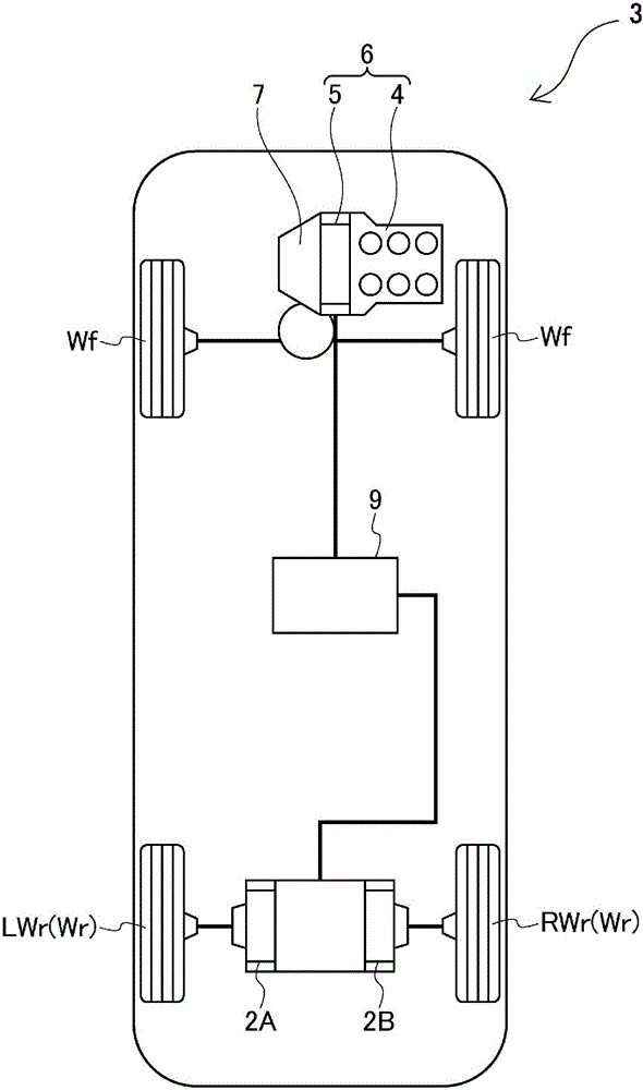
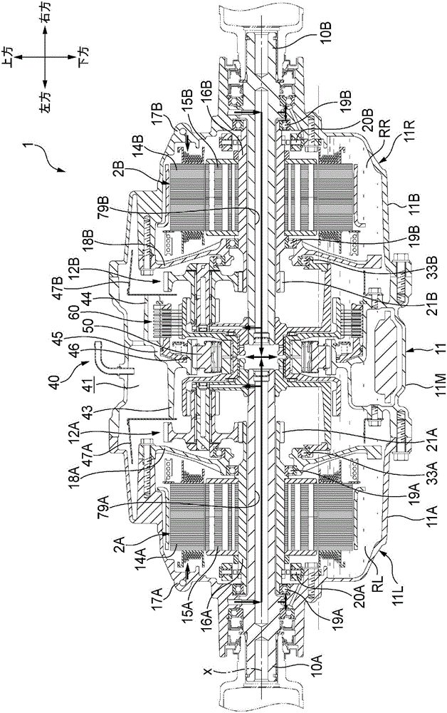
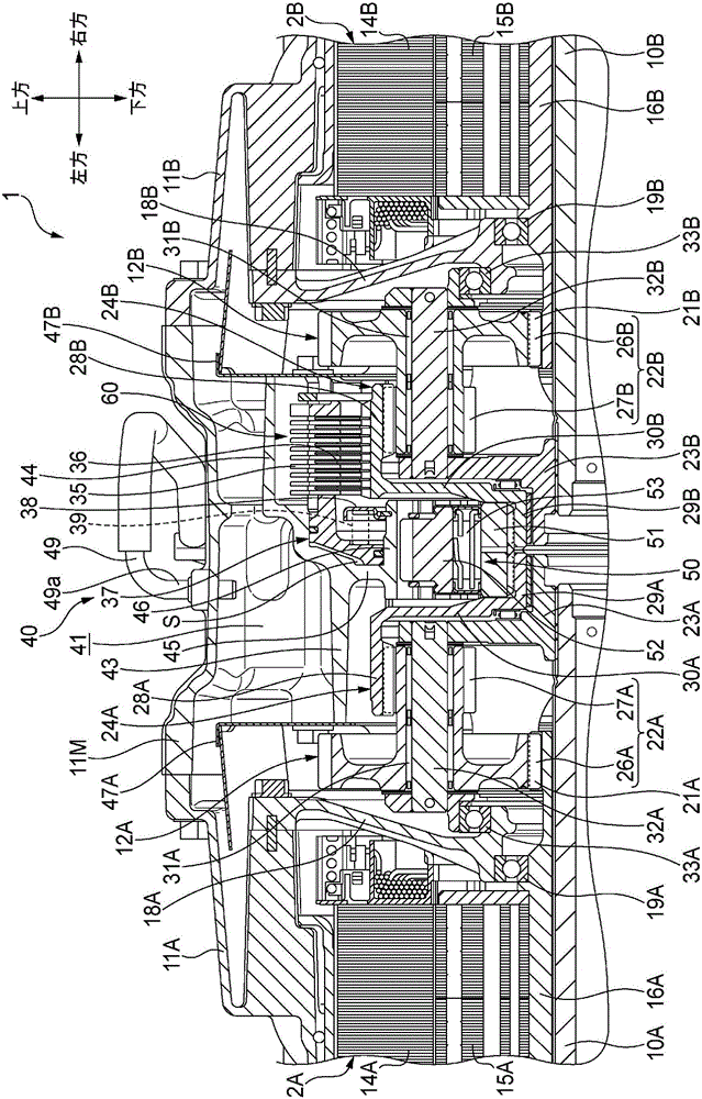
[0062] figure 1 The illustrated vehicle 3 is a hybrid vehicle having a driving device 6 (hereinafter referred to as a front-wheel drive device) in which an internal combustion engine 4 and an electric motor 5 are connected in series at the front of the vehicle. The transmission 7 transmits the transmission to the front wheels Wf. On the other hand, the driving device 1 (hereinafter referred to as the rear-wheel driving device 1 ) provided at a position lower than the floor (not shown) in the rear of the vehicle separately from the front-wheel driving device 6 device.) is transmitted to the rear wheels Wr (RWr, LWr). The rear wheel drive device 1 includes a first electric motor 2A and a second electric motor 2B, the power of the first electric motor 2A is transmitted to the left rear wheel LWr, and the power of the second electric motor 2B is transmitted to t...


PUM


Abstract

A vehicle (3) comprises a rear wheel drive device (1) which is supported on a subframe (13) by a bracket (81A, 81B) and a support unit (82A, 82B). The rear wheel drive device (1) comprises an extending portion (93A, 93B) which, from the rear wheel drive device (1), extends at an inclination to the vertical direction or extends in the horizontal direction, and which is formed such that, when an external force of at least a prescribed magnitude acts on said rear wheel drive device (1) and displaces an object mounted on said rear wheel drive device (1) by at least a prescribed amount, said extending portion (93A, 93B) contacts the upper surface (13f) of a joining flange (13e) on the subframe (13).

Description

technical field [0001] The present invention relates to a vehicle having a load supported by a frame member via a support mechanism. Background technique [0002] Electric vehicles such as electric vehicles and hybrid vehicles include a motor for driving the vehicle as a mounted object. The electric motor and the like for driving the vehicle are heavy objects, so if they are displaced toward the passenger space side during a collision, there is a possibility of a mechanical adverse effect. [0003] Therefore, conventionally, there has been proposed a technique for controlling the displacement of a load on a vehicle at the time of a collision. For example, in the vehicle described in Patent Document 1, a weak portion on the side of the battery unit is formed on the bracket supporting the battery unit side of the power unit on the vehicle body, and a bracket on the opposite side of the battery unit is supported on the vehicle body. The weak portion on the opposite side is fo...

Claims


Application Information

Patent Timeline
IPC IPC(8): B60K1/00
CPCB60K1/02B60K2001/001B60K1/00B60K7/0007B60K2007/0046B60K2007/0092B60Y2306/01B60K17/046B60Y2400/427B60Y2200/92B60Y2400/82Y10S903/906Y10S903/951Y02T10/72B60K6/00B60Y2200/91B60K28/14B62D21/15B60K6/26B60K6/40B60K6/52B60K2006/266
Inventor 山田贤矢崎学小野浩一
Owner HONDA MOTOR CO LTD
Why Eureka
Try Eureka