
Ultrasonic treatment device and ultrasonic operation system

A technology for treating instruments and ultrasonic waves, which is applied in the fields of ultrasonic treatment instruments and ultrasonic surgical systems, and can solve the problem that the driving power supply cannot detect the failure of the ultrasonic treatment instruments.

Active Publication Date: 2011-09-07
OLYMPUS CORP
View PDF5 Cites 26 Cited by
  • Summary
  • Abstract
  • Description
  • Claims
  • Application Information

AI Technical Summary

Problems solved by technology

Therefore, in the ultrasonic treatment process, in the event that the tip of the probe is damaged or the ultrasonic treatment instrument fails, the fault detection system with the above structure may not be able to detect the failure of the ultrasonic treatment instrument by the drive power supply.

Method used


Image

  • Ultrasonic treatment device and ultrasonic operation system
  • Ultrasonic treatment device and ultrasonic operation system
  • Ultrasonic treatment device and ultrasonic operation system

Examples


Embodiment Construction

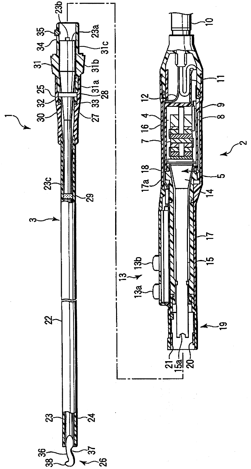
[0024] Below, refer to Figure 1 to Figure 9 The first embodiment of the present invention will be described. Figure 8 The overall schematic structure of the ultrasonic surgery system provided with the ultrasonic treatment instrument 1 of the first embodiment is shown. exist Figure 8 Among them, reference numeral 51 is a driving power source. The hand piece 2 and the foot switch 52 of the ultrasonic treatment tool 1 are connected to the drive power source 51 .

[0025] figure 1 The overall schematic structure of the ultrasonic treatment instrument 1 according to this embodiment is shown. The ultrasonic treatment instrument 1 has a handpiece 2 and a probe unit 3 .

[0026] The handpiece 2 has a housing 4 and a bolt-on Langevin type ultrasonic transducer (BLT) 5 . Case 4 is formed of an electrically insulating resin material. The above-mentioned BLT5 is built in the inside of the case 4 . The BLT 5 has a plurality of piezoelectric elements 7 and two electrodes 8 , 9 . ...


PUM


Abstract

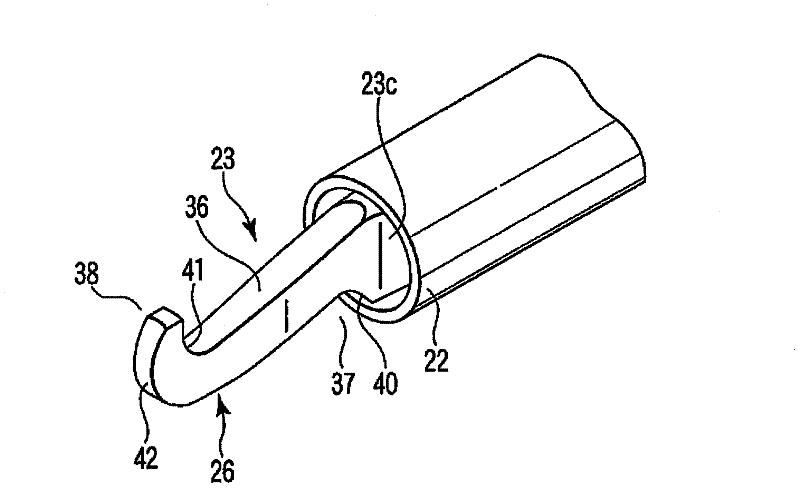
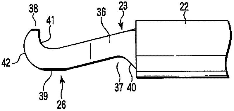
The invention provides an ultrasonic treatment device and an ultrasonic operation system. The ultrasonic treatment device provided with a sheath (22) having a front end and a base end, and also with an ultrasonic probe (23) having an inserted section (23c) which is inserted in the sheath (22) and is located in the sheath (22) and also having a hook-shaped treating section (26) which is provided to the front end of the inserted section (23c) and projects from the sheath (22). The treating section (26) has an extending section (36) extending forward and obliquely downward from an upper portion of the front end of the inserted section (23c). A recess (37) is formed in the underside of the extending section (36).

Description

technical field [0001] The present invention relates to an ultrasonic treatment instrument and an ultrasonic surgical system for incising and other treatments of living tissue by ultrasonic vibration. Background technique [0002] As an example of a general ultrasonic treatment instrument for incising and other treatments of living tissue using ultrasonic waves, for example, the ultrasonic treatment instrument disclosed in Patent Document 1 is generally known. In this ultrasonic treatment instrument, an operation part on the operator's side is connected to the base end part of the elongated insertion part. An ultrasonic vibrator for generating ultrasonic vibrations is disposed in the operation section. A treatment unit for treating living tissue is arranged at the front end of the insertion unit. [0003] The insertion part has an elongated circular tubular sheath. A rod-shaped vibration transmission member (probe) penetrates inside the sheath. The base end portion of th...

Claims


Application Information

Patent Timeline
Patent Type & Authority Applications(China)
IPC IPC(8): A61B18/00
CPCA61B18/04A61B2017/00349A61B2017/320072A61B17/320068A61B2019/4847A61B2090/0809A61B2017/320069A61B2017/320082A61B2017/320073
Inventor 吉岭英人
Owner OLYMPUS CORP
Learn More