Method and apparatus for measuring resistivity of formations

A technology of resistivity and equipment, which is applied in the field of measuring formation resistivity and equipment, and can solve the problems of long instrument length and increased survey depth

Inactive Publication Date: 2011-09-07
PRAD RES & DEV LTD
View PDF4 Cites 2 Cited by
  • Summary
  • Abstract
  • Description
  • Claims
  • Application Information

AI Technical Summary

Problems solved by technology

[0006] However, the problem with having transmitters above and below the receiver pair is that in order to achieve long transmitter-receiver separations and often deep resistivity measurements, the instrument must be long because the depth of investigation will decrease as the transmitter separation increases. increase

Method used


Image

  • Method and apparatus for measuring resistivity of formations
  • Method and apparatus for measuring resistivity of formations
  • Method and apparatus for measuring resistivity of formations

Examples


Embodiment Construction

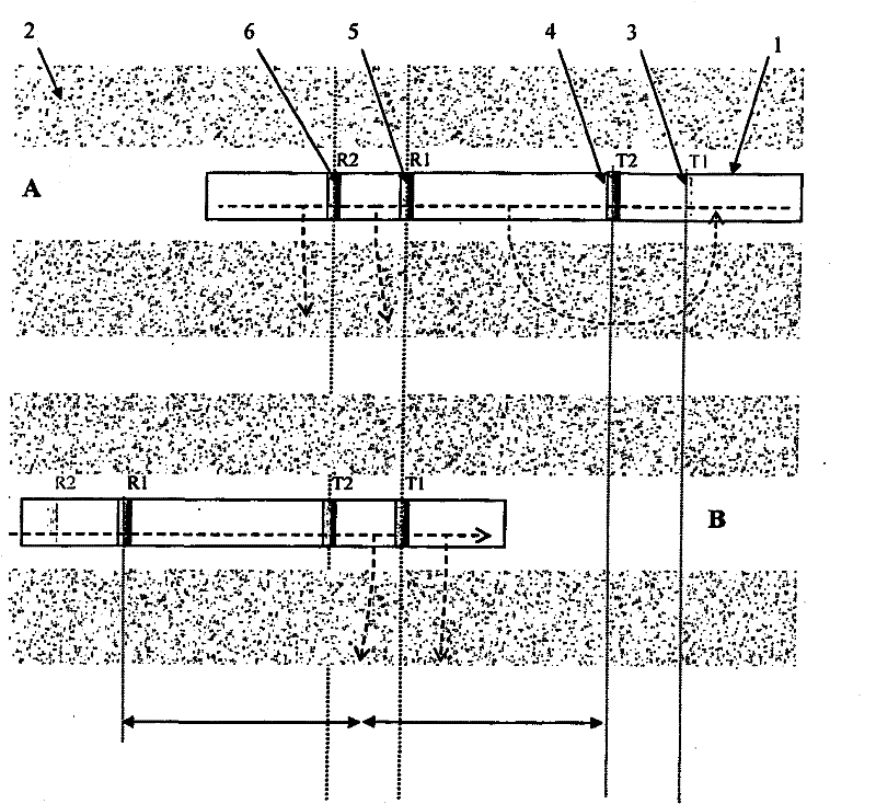
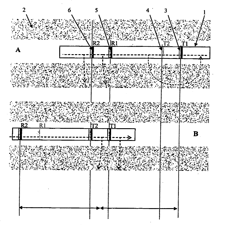
[0031] The invention comprises a device for measuring resistivity in an earth formation 1 having an elongated body 2 with two transmitter antennas 3,4 and two receiver antennas 5,6 mounted on a conductive body 2 . The two transmitters are positioned on the instrument body such that they are on the same side of the two receivers. In the case of an LWD instrument, the electrical conductor may be a drill collar.

[0032] When energized by a sinusoidal current, the transmitter induces a voltage in the loop formed by the drill collar and formation. This voltage, which can be measured by the secondary winding, induces a current in the formation and borehole mud.

[0033] The receiver measures the current flowing on the drill collar where the receiver is located. A pair of receivers is capable of measuring the difference in axial current, which is equal to the radial current entering the formation between the two receivers.

[0034] While the current standard method for focusing ...


PUM


Abstract

An apparatus for determining the resistivity of formation (2) surrounding a borehole comprising: an elongate conductive body (1); a pair of transmitter antennas comprising first and second antennas (3,4) mounted on the body for inducing a current in the formation; and a pair of receiver antennas comprising first and second antennas (5,6) mounted on the body for measuring an axial current running in the tool body at the location of the receivers; wherein the pair of transmitter antennas is located to one side of the pair of receiver antennas.

Description

technical field [0001] The present invention relates to measuring the resistivity of formations surrounding a wellbore. Background technique [0002] Resistivity logging tools have been used for many years to measure the resistivity of formations surrounding wellbores. [0003] In a typical resistivity measurement instrument, a pair of receivers is located between two transmitters. When energized by a sinusoidal current, the transmitter induces a voltage in the loop formed by the drill collar and formation. This voltage, which can be measured by the secondary winding, induces a current in the formation and borehole mud. The receiver measures the current flowing on the drill collar at the location where the receiver is located. A pair of receivers is capable of measuring the difference in axial current, which is radial current into the formation between the two receivers. [0004] The transmitter-receiver pair measures the conductance of the formation along the establishe...

Claims


Application Information

Patent Timeline
Patent Type & Authority Applications(China)
IPC IPC(8): G01V3/28
CPCG01V3/28
Inventor D·迪翁I·迪堡
Owner PRAD RES & DEV LTD
Why Eureka
Try Eureka