A power supply system and method for controlling a mechanically commutated electric motor

A technology of mechanical commutation and power supply system, which is applied in the direction of control system, AC motor control, excitation or armature current control, etc.

Inactive Publication Date: 2011-09-07
IDE ASSOCS (IOM) LTD
View PDF5 Cites 2 Cited by
  • Summary
  • Abstract
  • Description
  • Claims
  • Application Information

AI Technical Summary

Problems solved by technology

[0007] The object of the present invention is to detect the commutation of a mechanically commutated motor in order to overcome these problems of arcing etc.

Method used


Image

  • A power supply system and method for controlling a mechanically commutated electric motor
  • A power supply system and method for controlling a mechanically commutated electric motor
  • A power supply system and method for controlling a mechanically commutated electric motor

Examples


Embodiment Construction

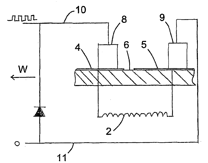
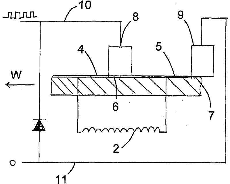
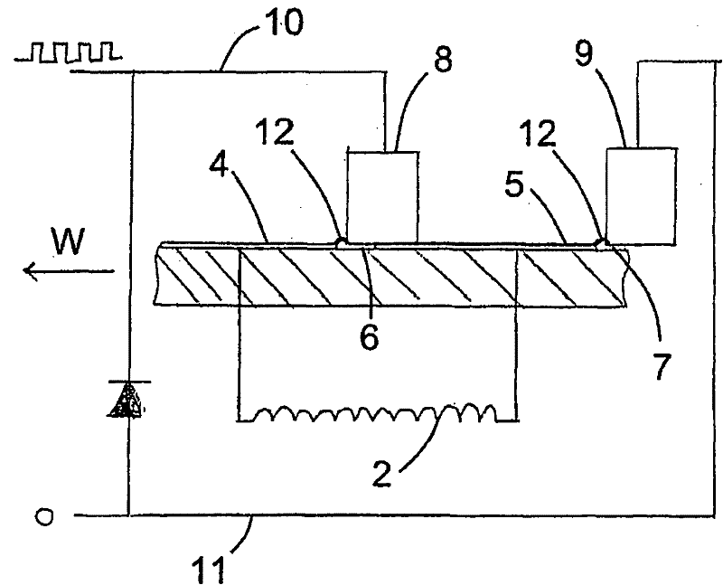
[0037] figure 1 drawn in image 3 and 4A very simplified diagram of the commutator equipment used in a mechanically commutated motor 1. A commutator is a rotary switch that changes the polarity of the current supplied to the magnetizing winding 2 of the electromagnet and thus the polarity of the electromagnet. Because the commutator rotates, it is usually cylindrical, but for illustration purposes it is drawn here as a straight line. The schematically drawn commutator includes a substrate 3 that rotates with the motor rotor in the direction indicated by arrow W. A plurality of contact pads 4, 5 separated by gaps 6, 7 are positioned on the substrate surface. For illustration purposes only two contact pads 4, 5 are drawn. The contact pads 4,5 are engaged by two brushes 8,9 so that current flows to the contact pads 4 via the brushes 8 from a power source (not shown) connected to the current supply lead 10. Current flows from contact pad 4 through magnetizing winding 2 to an...


PUM


Abstract

The invention relates to a method for providing a trigger signal in response to the commutation of a mechanically commutated electric motor (1). The method comprising the steps of providing a mechanically commutated electric motor (1), providing a power supply for said mechanically commutated electric motor via electrical supply leads (10, 11) from power supply circuitry, providing a filter (15) connected to said electrical supply leads (10, 11), detecting with said filter (15) a voltage spike occurring at commutation, outputting from said filter (15) said trigger signal.

Description

technical field [0001] The present invention relates to a method for providing a trigger signal in response to commutation of a mechanically commutated motor. The invention also relates to a power supply system for a mechanically commutated electric motor. Background technique [0002] Mechanically commutated motors are known in the art, ie motors in which the brushes and commutator arrangement change the polarity of the current in the rotor windings within the magnetic field generated by the stator as the rotor rotates. The magnetic field in this type of motor can be generated by permanent magnets or electromagnets. If the field is produced by electromagnets, the current in the windings producing the stator's field can be supplied by a separate magnetizing current, or it can be supplied by the same current as the current through the rotor windings. The latter is generally called a universal motor, since it is also well suited for AC, as long as the AC frequency is not too...

Claims


Application Information

Patent Timeline
IPC IPC(8): H02P7/29
CPCH02P7/29H02P25/14
Inventor P·B·费什C·M·P·维拉德森
Owner IDE ASSOCS (IOM) LTD
Why Eureka
Try Eureka