Liquid filling machine

A filling machine and liquid technology, applied in liquid bottling, liquid processing, packaging and other directions, can solve the problems of frequent start-up and easy damage, decreased measurement accuracy, and reduced concentration, etc., to simplify the control of liquid level, improve reliability, The effect of fast filling

Inactive Publication Date: 2011-09-14
LUZHOU JIANGXU MACHINERY MFG
View PDF3 Cites 17 Cited by
  • Summary
  • Abstract
  • Description
  • Claims
  • Application Information

AI Technical Summary

Problems solved by technology

[0013] 1) The cost of the equipment is extremely high and the structure is relatively complicated (in order to keep the liquid level consistent, the backflow device system is adopted at home and abroad, that is, a bypass liquid storage tank, a float switch of the bypass liquid storage tank, a sanitary explosion-proof pump, etc. are installed);
[0014] 2) The error of filling capacity is large: the consistency of the liquid level in the liquid storage tank of the filling machine is particularly strict. If the liquid level difference is 1mm, the filling accuracy will deviate by 1mL, and the rotary filling machine is working. The liquid storage tank is a kind of circular motion with centripetal force, so it is difficult to control the liquid level to maintain consistency, resulting in large errors in filling measurement;
[0015] 3) The industrial computer has many control points and is complex, and it is easy to be damaged when it is started frequently;
[0016] 4) The liquid is poorly sealed during the filling process, the liquid is easy to volatilize and reduce the concentration, and the safety is not high;
[0017] 5) If the machine debugging is not normal, the liquid often overflows to the ground;
[0018] 6) Large volume takes up space
[0019] 7) Due to the fast operation speed of the rotary filling machine, the centripetal force is relatively large, and the liquid level in the liquid storage tank will form a "concave" shape, and the measurement accuracy will decrease
[0032] 1) The cost of equipment is extremely high;
[0033] 2) The structure is very complicated. The number of cylinders and pneumatic solenoid valves is twice as many as that of the filling machine invented this time. Each filling head must be equipped with 2 cylinders and pneumatic solenoid valves. In addition, each filling head must be equipped with a Magnetostrictive liquid level sensor;
[0034] 3) The industrial computer has a lot of control points, and it is easy to be damaged when it is started frequently

Method used


Image

  • Liquid filling machine
  • Liquid filling machine
  • Liquid filling machine

Examples


Embodiment 1

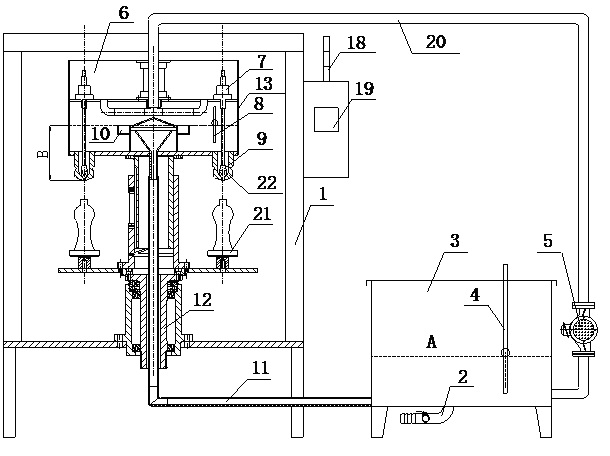
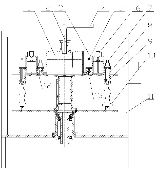
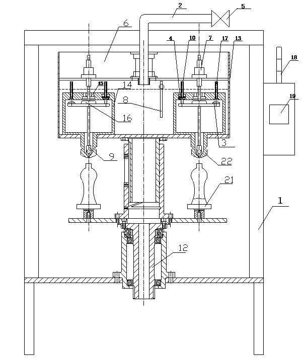
[0080] Such as image 3 As shown, a liquid filling machine includes a frame 1, a liquid inlet pipe 2, a sealing gasket 3 of the air inlet pipe before filling, a sealing gasket 4 of the air inlet pipe during filling, a liquid inlet ball valve 5, and a filling machine liquid storage tank 6 , cylinder 7, filling machine liquid storage tank float switch 8, filling valve spool 9, filling in progress vent pipe 10, main drive shaft 12, vent hole 13, constant liquid level cup 14, liquid inlet 15, Liquid inlet sealing gasket 16, vent pipe 17 before filling, warning light 18, touch screen 19, bottle tray 21 and filling head 22, wherein, liquid inlet pipe 2 passes through the upper end of frame 1 and directly stores liquid with the filling machine The upper end of the tank 6 is connected, and the liquid storage tank 6 of the filling machine is equipped with a float switch 8 of the liquid storage tank of the filling machine and multiple groups of cylinders 7. The lower end of each group o...


PUM


Abstract

The invention discloses a liquid filling machine and belongs to the field of filling equipment. The liquid filling machine comprises a liquid inlet pipe and a filling machine liquid storage pot, wherein the liquid inlet pipe passes through the upper end of a stander and is directly connected with the upper end of the filling machine liquid storage pot; and a filling machine liquid storage pot floating switch and a plurality of groups of air cylinders are arranged in the filling machine liquid storage pot. In the liquid filling machine, one air cylinder controls one filling head; an equal height counting mode of the inner liquid level of the liquid storage pot is not required; a constant liquid level cup type stable liquid level is adopted, so one filling head needs only one air cylinder, and the counting and filling precision is high; the filling machine is easy to process and the number of output points of an industrial control computer is small, so the cost can be reduced by over 1 / 2; the liquid filling machine is durable, the liquid level is easy to control, and the reliability is enhanced; backflow control is not needed, so the power is saved; the liquid filling machine is easy in maintenance, good in sealing property and safe; liquid is hard to volatilize during filling; the filling precision is enhanced and the filling speed is high; and the liquid filling machine can be widely applied to rotary gas-free liquid filling machines, discharging gas-free liquid filling machines and the like.

Description

technical field [0001] The invention relates to a packaging device, in particular to a filling machine. Background technique [0002] Type here the technical field description paragraph At present, there are two main structures and control methods of common liquid filling machines: the first one is the equal height liquid level in the single-cylinder liquid storage tank and the backflow control method; the second one is External dual cylinders control each filling head, without the need for a constant metering method for the liquid level of the liquid storage tank. [0003] Among them, the first method of controlling liquid level and backflow in the single-cylinder liquid storage tank is as follows: figure 1 As shown, including frame, alarm light, touch screen, liquid inlet pipe, bypass liquid storage tank, bypass liquid storage tank float switch, sanitary explosion-proof pump, filling machine liquid storage tank, air cylinder, filling machine liquid storage tank Float swi...

Claims


Application Information

Patent Timeline
Patent Type & Authority Applications(China)
IPC IPC(8): B67C3/00B67C3/22B67C3/26
Inventor 古华贵
Owner LUZHOU JIANGXU MACHINERY MFG
Why Eureka
Try Eureka