Light emitting diode (LED) lamp with front and rear cavity structures
A technology of LED lamps and LED lamp beads, which is applied in the parts of lighting devices, semiconductor devices of light-emitting elements, cooling/heating devices of lighting devices, etc. Problems such as weak connection and increased heat dissipation efficiency of the heat sink can prevent rain and snow from penetrating into the lamp, prevent the lamp from being easily damaged, and easily adjust the connection angle
- Summary
- Abstract
- Description
- Claims
- Application Information
AI Technical Summary
Problems solved by technology
Method used
Image
Examples
Embodiment 1
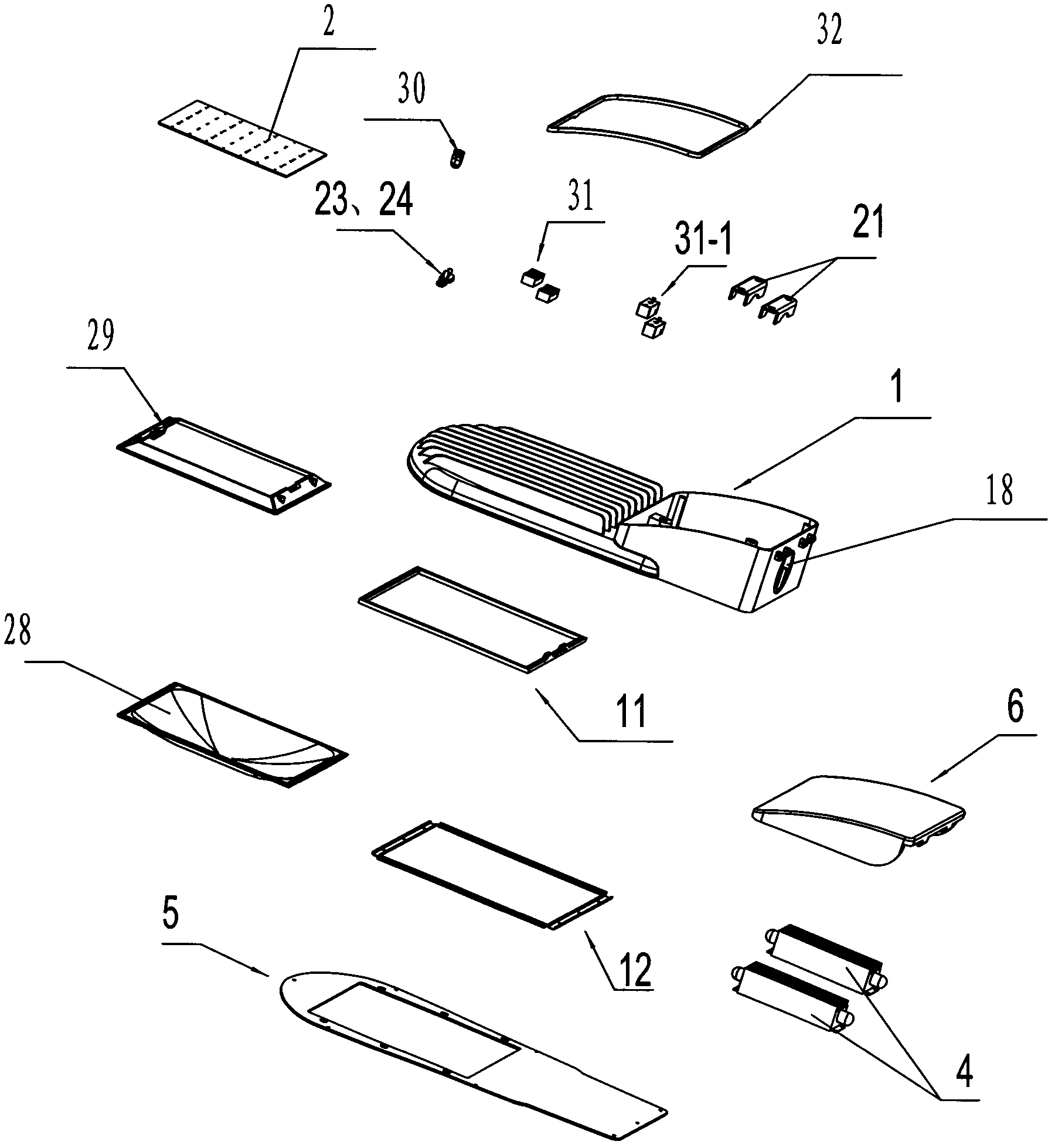
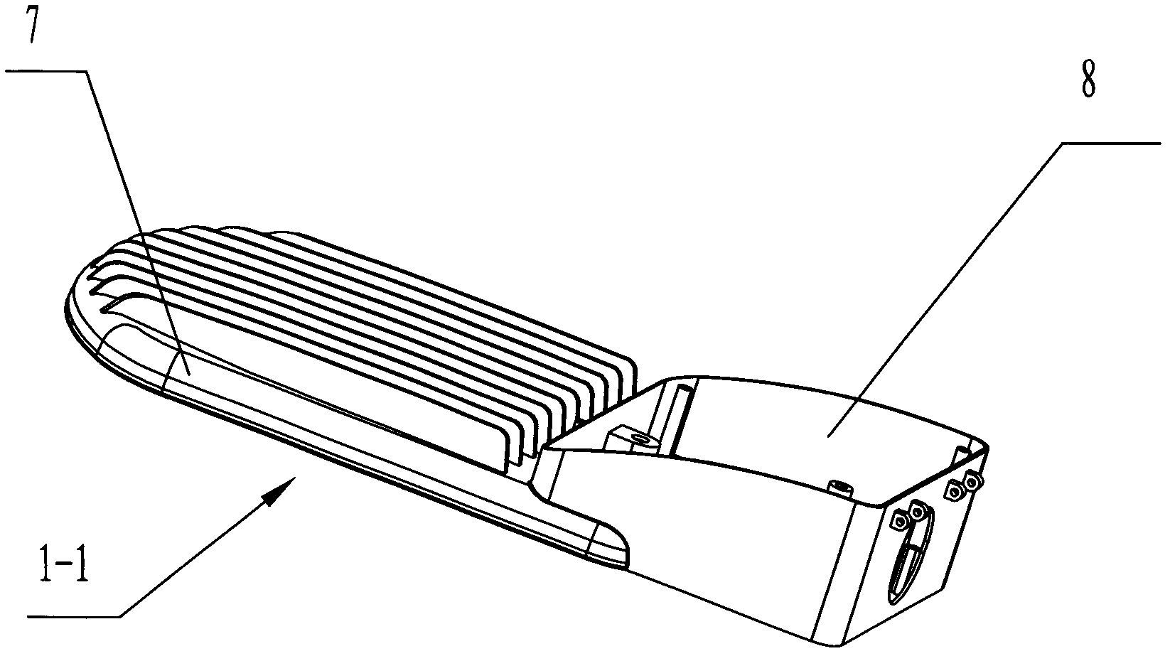
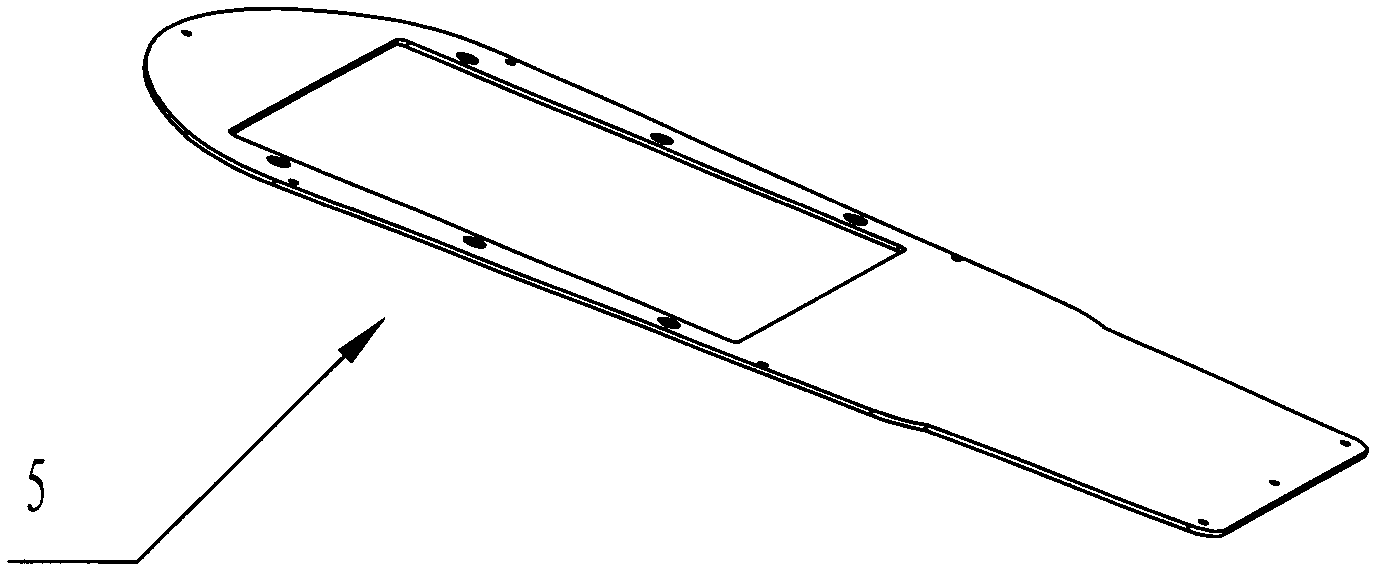
[0048] like Figure 1 to Figure 4 As shown, an LED lamp with a front and rear cavity structure includes a lamp base housing 1, an LED aluminum substrate 2, several LED lamp beads 3 and a power supply 4. The lamp base housing 1 includes a housing main body 1-1 and The heat sink 1-2, the heat sink 1-2 is composed of several longitudinally evenly distributed heat dissipation ribs 1-3, the LED lamp beads 3 are installed on the front of the LED aluminum substrate 2, and are evenly distributed, and the one has The LED lamp with the front and rear chamber structure also includes a bottom cover 5 and a rear cover 6. The lamp housing 1 includes a front part and a rear part, and the bottom cover 6 includes an upper part and a lower part. The front part of the lamp housing 1 and the bottom cover The upper part of 5 forms the front chamber 7, the rear part of the lamp housing 1 and the rear cover 6 form the rear chamber 8, the LED aluminum substrate 2 and several LED lamp beads 3 are arra...
Embodiment 2-5
[0054] In Embodiment 2-5, the elevation angle α of the LED street lamp composed of the above drawings and the installation direction of the cylindrical light pole 16 and the direction of the bottom cover 5 is shown in the following figure:
[0055]
[0056] The method of adjusting the elevation angle of LED street lamps: In Embodiments 2, 3, 4, and 5, first loosen the light pole pressure plate screw 22, and then support the upper end of the cylindrical light pole 16 on the adjustment step b of the adjustment baffle 20 , c, d, e, and then pass the light pole pressure plate screw 22 through the light pole pressure plate 21, screw it into the pressure plate screw hole 19-1, and tighten it, the cylindrical light pole 16 is closely connected with the main body 1-1 of the lamp housing up.
[0057] The rest are the same as embodiment 1.
PUM
 Abstract
Description
Claims
Application Information
 - R&D
- Intellectual Property
- Life Sciences
- Materials
- Tech Scout
- Unparalleled Data Quality
- Higher Quality Content
- 60% Fewer Hallucinations
Browse by: Latest US Patents, China's latest patents, Technical Efficacy Thesaurus, Application Domain, Technology Topic, Popular Technical Reports.
© 2025 PatSnap. All rights reserved.Legal|Privacy policy|Modern Slavery Act Transparency Statement|Sitemap|About US| Contact US: help@patsnap.com


