Top-outlet side-inlet type household dehumidifier

A technology of dehumidifier and side air intake, which is applied in the field of household dehumidifiers with top air outlet and side air intake, which can solve the problems of being unable to place the dehumidifier against the wall, increasing the installation space of the dehumidifier, and restricting the appearance design of the dehumidifier. Achieve the effect of increasing the utilization rate of air intake, improving the overall aesthetics and increasing the three-dimensional effect

Inactive Publication Date: 2011-09-14
GUANGDONG CHIGO AIR CONDITIONING
View PDF5 Cites 4 Cited by
  • Summary
  • Abstract
  • Description
  • Claims
  • Application Information

AI Technical Summary

Problems solved by technology

The rear air outlet method is adopted. Since the air outlet is placed directly behind the back panel of the household dehumidifier, the dehumidifier must be kept at a certain distance from the wall or furniture when the whole machine is running, so as to ensure the smooth air outlet of the whole machine when the dehumidifier is running. As a result, it is impossible to place the dehumidifier against the wall, which increases the installation space of the dehumidifier and reduces the convenience of use; while the traditional front panel air intake method needs to reserve a large area directly in front of the front panel of the household dehumidifier. The large air inlet restricts the appearance design of the dehumidifier and affects the aesthetics of the product

Method used


Image

  • Top-outlet side-inlet type household dehumidifier
  • Top-outlet side-inlet type household dehumidifier
  • Top-outlet side-inlet type household dehumidifier

Examples


Embodiment Construction

[0024] In order to enable those skilled in the art to better understand the technical solutions of the present invention, the present invention will be further described in detail below in conjunction with the accompanying drawings and specific embodiments.

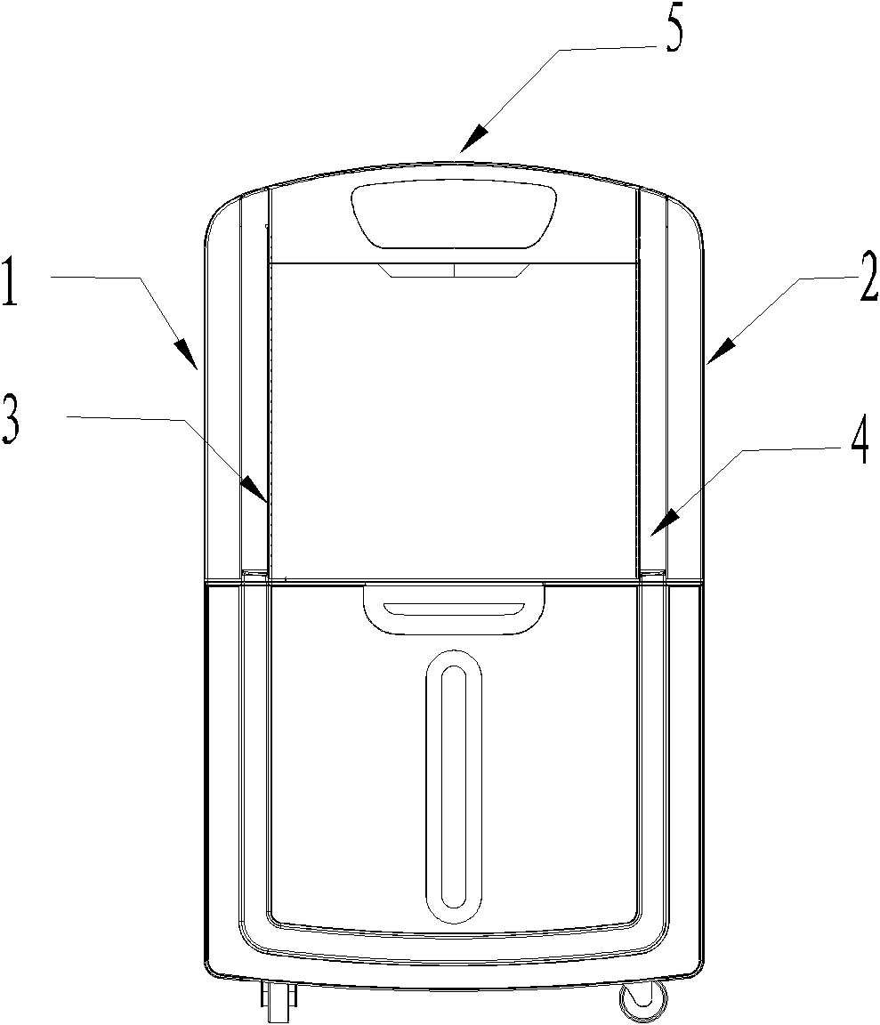
[0025] The core of the present invention is that the dehumidifier is designed with an air inlet structure on the top air outlet side. see figure 1 , showing the positions of the top air outlet 5, the first side air inlet 1 to the fourth side air inlet 4 of the top air outlet side air inlet type household dehumidifier (hereinafter referred to as the dehumidifier) ​​of the present invention in the complete machine, and the following are respectively about the positions The top air outlet structure and side air inlet structure design of the dehumidifier will be described in detail.

[0026] 1. Top outlet air structure design

[0027] The top air outlet structure of the dehumidifier of the present invention is realized base...


PUM


Abstract

The invention discloses a top-outlet side-inlet type household dehumidifier, and the interior of the dehumidifier is divided into upper and lower layer structures by a middle separating plate (9), wherein an evaporator (6), a condenser (7) and a centrifugal fan volute (8) which are sequentially arrayed in parallel are supported in the upper layer structure by the middle separating plate (9); the evaporator (6) is placed at one side close to a front panel of the dehumidifier; a distance is reserved between the evaporator (6) and the condenser (7); an air-inducing side of the centrifugal fan volute (8) is parallel to a lateral heat-exchange side of the condenser (7); the direction of an air outlet of the centrifugal fan volute (8) is vertical upwards; the air outlet (5) is arranged on the top of a rear panel of the dehumidifier at the position corresponding to the air outlet of the centrifugal fan volute (8); and left air inlet and right air inlet are respectively formed on left and right side walls of the whole dehumidifier exterior at the positions corresponding to a windward side of the evaporator (6). By using the household dehumidifier, the settling space is reduced in the use process, the use convenience is promoted and the product is more beautiful.

Description

technical field [0001] The invention relates to a household dehumidifier, in particular to a household dehumidifier of the top air outlet side air intake type. Background technique [0002] At present, the air inlet and outlet methods of the existing integrated household dehumidifiers on the market generally adopt the rear air outlet and front air inlet methods. The rear air outlet is adopted. Since the air outlet is placed directly behind the back panel of the household dehumidifier, the dehumidifier must be kept at a certain distance from the wall or furniture when the whole machine is running, so as to ensure the smooth air outlet of the whole machine when the dehumidifier is running. As a result, it is impossible to place the dehumidifier against the wall, which increases the installation space of the dehumidifier and reduces the convenience of use; while the traditional front panel air intake method needs to reserve a large area directly in front of the front panel of t...

Claims


Application Information

Patent Timeline
Patent Type & Authority Applications(China)
IPC IPC(8): F24F1/02F24F13/06F24F13/08F24F13/20
Inventor 谢敏生王赛胡轩恒
Owner GUANGDONG CHIGO AIR CONDITIONING
Why Eureka
Try Eureka