Rotary cutting edge mounting structure for crusher and crusher using such mounting structure

An installation structure and crusher technology, which is applied in the field of rotating blade installation structure and crusher, can solve problems such as cracks or gaps at the front end of the superhard knife tip 8, and achieve the effect of reducing material costs

Inactive Publication Date: 2011-09-21
KINKI KK
View PDF5 Cites 9 Cited by
  • Summary
  • Abstract
  • Description
  • Claims
  • Application Information

AI Technical Summary

Problems solved by technology

[0005] Moreover, when the operation of shearing and crushing the object to be crushed is carried out by using the crusher 1 or continues for a certain period of time, cracks or chips may sometimes occur at the front end of the superhard blade tip 8.

Method used


Image

  • Rotary cutting edge mounting structure for crusher and crusher using such mounting structure
  • Rotary cutting edge mounting structure for crusher and crusher using such mounting structure
  • Rotary cutting edge mounting structure for crusher and crusher using such mounting structure

Examples


Embodiment Construction

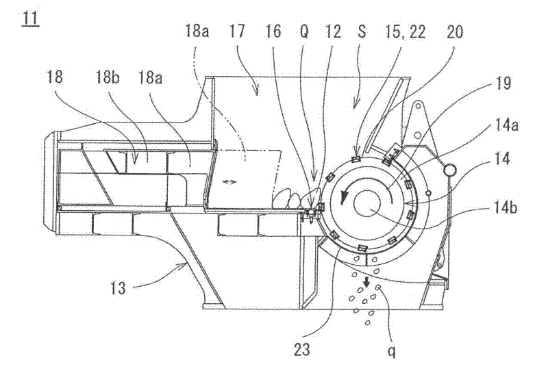
[0107] Refer to the following figure 1 Embodiment 1 of the rotary blade installation structure of the crusher of this invention and the crusher using this structure is demonstrated to FIG. 4. The shredder 11 is, for example, a single-shaft shredder, and is a device capable of shredding objects 12 to be shredded, such as waste wood, waste plastic, and used paper, into predetermined sizes. Furthermore, the purpose of crushing the object 12 to be crushed by the crusher 11 is to recycle the object to be crushed 12 such as waste as boiler fuel or agricultural materials.

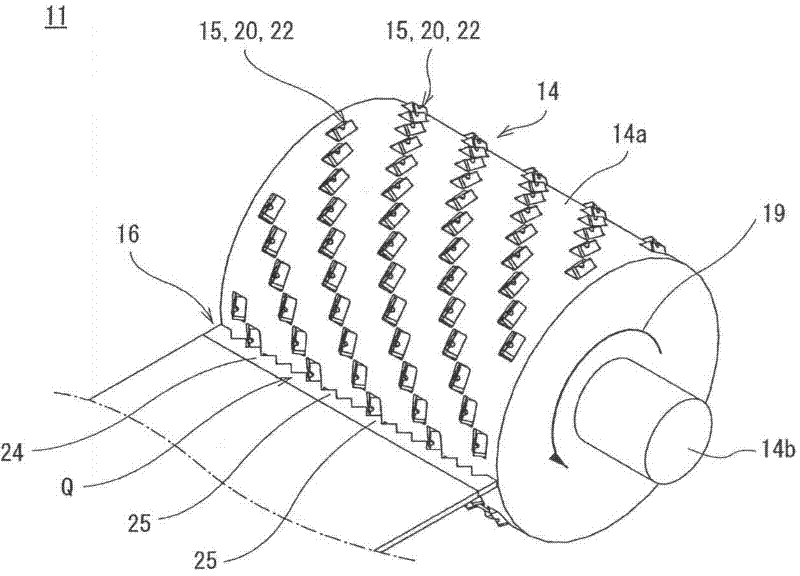
[0108] Crusher 11 AS figure 1 As shown, it includes a housing 13, a rotor 14 arranged inside the housing 13, a plurality of rotating blades 15 mounted on the surface of the rotor 14, a fixed blade 16 disposed on the housing 13 and arranged along the surface of the rotor 14, The hopper 17 installed on the upper part of the housing 13 and the push rod 18 installed on the side of the housing 13 .

[0109] The ho...


PUM


Abstract

The invention provides a rotary cutting edge mounting structure for crusher and a crusher using such mounting structure, wherein the cutting edge portion is produced with a small size to improve the utilization ratio of resources, reduce the material cost of the cutting edge portion and allow the rotary cutting edge to be mounted on a rotor detachably conveniently. The crusher comprises a rotary rotor, a plurality of rotary cutting edges mounted on the surface of the rotor, and fixed cutting edges arranged on a housing to shear and crusher the crushed material between the rotary cutting edges, wherein the rotary cutting edge mounting structure for crusher comprises a plurality of mounting grooves processed on the surface of the rotor and provided with an even surface on bottoms thereof, wherein the rotary cutting edges are mounted on the inner side of the mounting grooves; the bottom surfaces of the rotary cutting edges are formed as even surfaces, and the rotary cutting edges are provided with a cutting edge portion for shearing and crushing the material to be crushed; the cutting edge portions are substantially triangle-shaped on front side faces formed as front sides thereof relative to the rotating direction of the rotary cutting edges.

Description

technical field [0001] The invention relates to a rotating blade installation structure of a crusher for shearing and crushing waste wood, waste plastics, old paper, etc. Install structure breakers. Background technique [0002] As an example of previous crushers, there are Figure 17(a) , Figure 17(b) The crusher shown (for example, refer to Patent Document 1). This shredder 1 is a shredder that shears and shreds objects to be shredded, such as waste wood and waste plastic, between a plurality of rotating blades 3 mounted on the surface of a rotor 2 and fixed blades provided on a fixing portion (not shown). And, if Figure 17(a) As shown, a plurality of plates 4 are detachably mounted on the outer peripheral surface of the rotor 2 with bolts 5 , and a plurality of mounting grooves 6 are formed on the surface of each plate 4 . And the rotating blade 3 is welded and installed on each mounting groove 6 . These rotating blades 3 are the same rotating blades and include a b...

Claims


Application Information

Patent Timeline
Patent Type & Authority Applications(China)
IPC IPC(8): B02C18/18B02C18/06
Inventor 和田直哉杉本章本田泰彦青田光弘黑田直宽井上安秀松本胜柁山博章竹元奈都记
Owner KINKI KK
Why Eureka
Try Eureka