
Tapping device for automatic lathe

A technology of automatic lathe and speed control device, which is applied in the direction of tangent device, other manufacturing equipment/tools, metal processing equipment, etc., can solve problems such as inability to accurately locate the stop position of the tapping head, easy wear of friction plates, and increased maintenance costs. , to achieve the effect of expanding the scope of processing applications, improving accuracy and improving processing efficiency

Inactive Publication Date: 2013-06-05
张家港名阳精密机械制造有限公司
View PDF0 Cites 0 Cited by
  • Summary
  • Abstract
  • Description
  • Claims
  • Application Information

AI Technical Summary

Problems solved by technology

Since the electromagnetic starter takes a long time to reach the required tapping torque after being triggered, the position that has not reached the tapping depth within the specified tapping time has been retracted, so that the stop position of the tapping head cannot be accurately located. When processing parts , there will be situations where the tapping is not in place, and the frequent start and stop of the electromagnetic clutch makes the friction plate easy to wear and increase the maintenance cost

Method used


Image

  • Tapping device for automatic lathe

Examples


Embodiment Construction

[0010] The tapping device for automatic lathes of the present invention will be further described in detail below through specific embodiments.

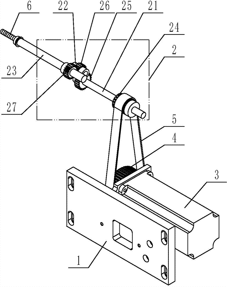
[0011] Such as figure 1 As shown, the tapping device used for automatic lathes includes a frame, on which a fixed base 1 and a speed regulating device 2 are arranged, a servo motor 3 is fixed on the fixed base 1, and a servo Pulley 4, described speed regulating device 2 comprises input shaft 21, intermediate shaft 22 and output shaft 23, and one end of input shaft 21 is provided with driven pulley 24, and driven pulley 24 passes belt 5 and servo pulley 4 The other end of the input shaft 21 is provided with an input gear 25, the intermediate shaft 22 is provided with an intermediate gear 26, the output shaft 23 is provided with an output gear 27, the input gear 25 is meshed with the intermediate gear 26, and the intermediate gear 26 and the output The gears 27 are meshed, and the output shaft 23 is provided with a tapping head 6 .

...


PUM


Abstract

The invention relates to a tapping device for an automatic lathe, comprising a rack, wherein the rack is provided with a servo motor and a speed regulating device, the output shaft of the servo motor is provided with a servo belt pulley, the speed regulating device comprises an input shaft and an output shaft, one end of the input shaft is provided with a driven belt pulley, the other end of the input shaft is provided with an input gear, the output shaft is provided with an output gear, the input gear and the output gear are meshed, the driven belt pulley is connected with the servo belt pulley by virtue of a belt, and the output shaft of the speed regulating device is provided with a tapping head. The tapping device provided by the invention is applicable to the automatic lathe, the stopping position of the tapping head can be accurately determined, the problem that tapping is uncompleted can be effectively solved, the tapping accuracy is greatly improved, the processing applicationrange of the automatic lathe is widened, and the processing efficiency is improved.

Description

technical field [0001] The invention relates to the field of machining equipment, in particular to a tapping device for an automatic lathe. Background technique [0002] At present, when tapping parts on an automatic lathe: after the automatic lathe runs to the tapping position, the micro switch is triggered by an external mechanical action to generate an electrical signal to realize the operation of the electromagnetic starter, which is transmitted to the tapping shaft through the synchronous belt for implementation. Tapping, after the tapping is in place, the micro switch is triggered by an external mechanical action to generate an electrical signal to make the electromagnetic brake brake. Since the electromagnetic starter takes a long time to reach the required tapping torque after being triggered, the position that has not reached the tapping depth within the specified tapping time has been retracted, so that the stop position of the tapping head cannot be accurately loc...

Claims


Application Information

Patent Timeline
Patent Type & Authority Patents(China)
IPC IPC(8): B23G1/16B23P23/02
Inventor 林荣芳
Owner 张家港名阳精密机械制造有限公司
Learn More