Automatic clamping and automatic clamping loosening threading machine and work method thereof

An automatic clamping and threading machine technology, which is applied to the accessories of toolholders, thread cutting machines, manufacturing tools, etc., can solve the problems of restricting threading machines, large energy loss, and limited automation, so as to expand the processing application range and reduce Production cost, effect of long-lasting clamping function

Inactive Publication Date: 2016-08-31
SHAOXING JIANHUA METAL LOGISTICS CO LTD
View PDF7 Cites 1 Cited by
  • Summary
  • Abstract
  • Description
  • Claims
  • Application Information

AI Technical Summary

Problems solved by technology

[0002] At present, all the threading machines are used in the field of manual impact chucks. Both the upper and lower parts need to be manually impacted on the chucks, which is labor-intensive and time-consuming, which restricts the upgrade of the automation of the threading machines. In the field of rotating automatic chucks In use, in addition to the main power for the main shaft to run, the equipment also needs auxiliary power to support the automatic chuck. The auxiliary power is divided into pneumatic and hydraulic. High cost and huge energy loss limit the promotion of automation

Method used


Image

  • Automatic clamping and automatic clamping loosening threading machine and work method thereof
  • Automatic clamping and automatic clamping loosening threading machine and work method thereof
  • Automatic clamping and automatic clamping loosening threading machine and work method thereof

Examples


Embodiment Construction

[0017] The present invention will be further described below in conjunction with the accompanying drawings.

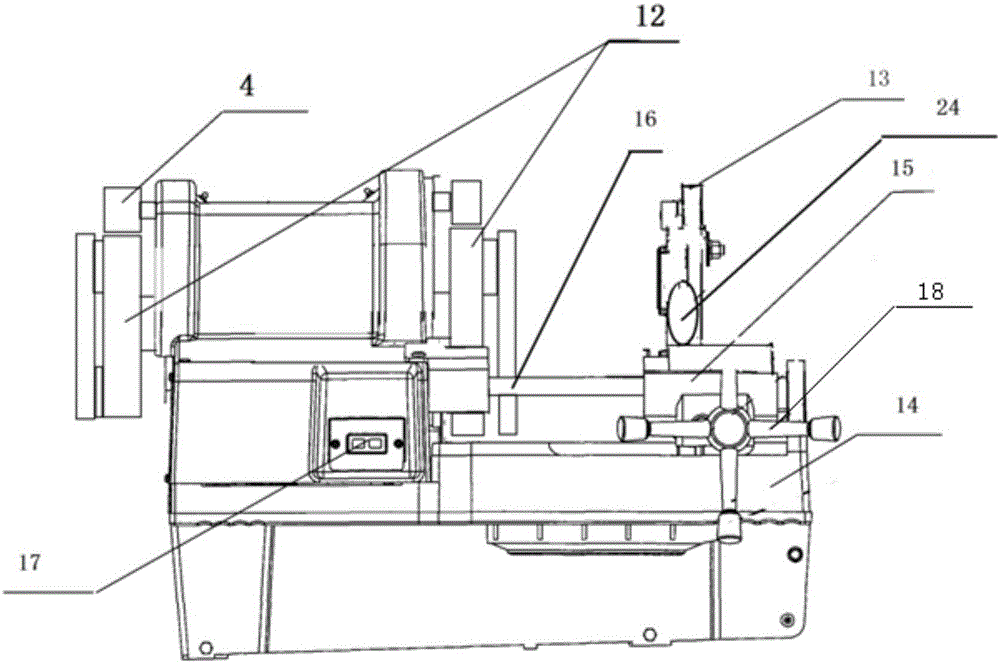
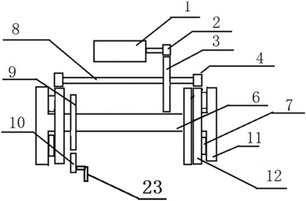
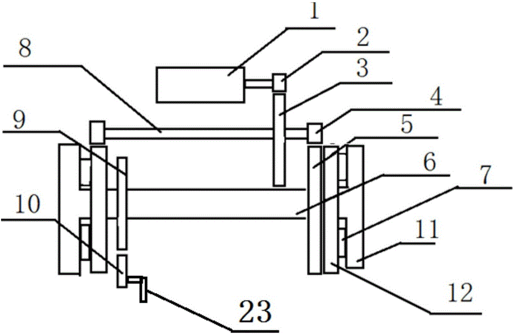
[0018] Such as Figure 1-3 As shown, the present invention comprises a frame 14 and a control device installed on the frame 14, a motor 1, a power deceleration transmission system, a chuck, a chuck shaft braking system, a carriage guide rail 16; the motor 1 and the chuck The shaft brake system is connected with the control device, and the control device is used to control the operation of the chuck shaft brake system and the motor 1; the power deceleration transmission system is connected with the motor 1; the chuck is fixedly installed on the chuck On the chuck shaft of the shaft brake system, the chuck is connected to the drive wheel 4 of the power reduction transmission system in transmission, and the carriage guide rail 16 is provided with a carriage 15, and the carriage 15 is provided with a die head 13 and a slide Frame advance and retreat handle 18. In the pre...


PUM


Abstract

The invention discloses an automatic clamping and automatic clamping loosening threading machine and a work method thereof. The automatic clamping and automatic clamping loosening threading machine comprises a rack, a control device, a motor, a power speed reduction transmission system, an automatic chuck system, a chuck shaft braking system and a sliding frame guide rail, wherein the control device, the motor, the power speed reduction transmission system, the automatic chuck system, the chuck shaft braking system and the sliding frame guide rail are installed on the rack. The motor and the chuck shaft braking system are connected with the control device. The control device controls the motor and the chuck shaft braking system. Power of the motor is transmitted to a chuck through the power speed reduction transmission system. The chuck completes the process of automatic clamping after the starting of the threading machine and the process of automatic clamping loosening after the shutdown of the threading machine under the cooperation of the chuck shaft braking system. By means of the automatic clamping and automatic clamping loosening threading machine and the work method thereof, power is completely provided by the main motor, power maintenance is not needed during clamping, power transmission is totally completed through mechanical transmission, and therefore the production cost is reduced; in addition, during use, the motor does not need to stop in the clamping and machining processes, and one-time operation on the processes of clamping, machining, clamping loosening and the like in the whole process is supported; and the technical nodes of the threading machine on automatic application are avoided.

Description

technical field [0001] The invention relates to the technical field of threading machines, in particular to an automatic clamping and automatic loosening threading machine and its working method. Background technique [0002] At present, all the threading machines are used in the field of manual impact chucks. Both the upper and lower parts need to be manually impacted on the chucks, which is labor-intensive and time-consuming, which restricts the upgrade of the automation of the threading machines. In the field of rotating automatic chucks In use, in addition to the main power for the main shaft to run, the equipment also needs auxiliary power to support the automatic chuck. The auxiliary power is divided into pneumatic and hydraulic. The high cost and huge energy loss limit the promotion of automation. Contents of the invention [0003] Aiming at the deficiencies of the prior art, the present invention provides an automatic clamping and automatic loosening threading mac...

Claims


Application Information

Patent Timeline
Patent Type & Authority Applications(China)
IPC IPC(8): B23B31/02B23B31/169B23G1/44B23G1/04
CPCB23B31/023B23B31/16B23B2260/002B23B2260/12B23G1/04B23G1/44
Inventor 平春华
Owner SHAOXING JIANHUA METAL LOGISTICS CO LTD
Why Eureka
Try Eureka