Power deceleration transmission system of threading machine

A technology of transmission system and threading machine, which is applied in the direction of thread cutting machine, driving device, automatic in/out workpiece, etc., can solve the problems of large energy loss, complex pipeline, complex structure, etc., and achieve low production cost, high reliability, The effect of simple and reliable mechanical structure

Inactive Publication Date: 2017-11-24
SHAOXING JIANHUA METAL LOGISTICS CO LTD
View PDF0 Cites 0 Cited by
  • Summary
  • Abstract
  • Description
  • Claims
  • Application Information

AI Technical Summary

Problems solved by technology

[0002] At present, the power deceleration transmission system in the threading machine field is only used for threading and pipe cutting operations, which restricts the application of automatic chucks on the threading machine. When the threading machine is loading and unloading, it is necessary to manually hit the chuck , labor-intensive and time-consuming, which restricts the upgrade of the automation of the threading machine. As far as the field of the rotating automatic chuck is concerned, in addition to the main power for the main shaft to run, the equipment also needs auxiliary power to support the automatic chuck. The auxiliary power is divided into Pneumatic and hydraulic, the two kinds of power transmission pipelines are complex, with high leakage and failure, serious power loss, complex structure, high production cost and huge energy loss, which limit the promotion of automation

Method used


Image

  • Power deceleration transmission system of threading machine
  • Power deceleration transmission system of threading machine

Examples


Embodiment 1

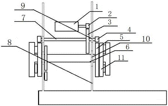
[0014] Embodiment 1: as figure 1 The power deceleration transmission system of a threading machine shown includes a power output wheel 2, a first driven wheel 3, a driving wheel 4, an output shaft 7, a chuck and a chuck shaft 6, and the power output wheel 2 is fixed On the output shaft of the motor 1, the first driven wheel 3 and the driving wheel 4 are fixed on the output shaft 7, the power output wheel 2 is in transmission cooperation with the driven wheel 3, and the output shaft 7 is arranged on the sleeve through a bearing 9. On the frame 8 of the wire machine, the chuck shaft 6 is set on the frame 8 through the rotation of the large bearing 10, and the chuck includes a driven wheel 5 and a flat screw disk 11, and the driven wheel 5 and the flat screw disk 11 are rotated and set On the chuck body of the chuck, the driving wheel 4 is in transmission connection with the plane screw disk 11, and the plane screw disk 11 is connected with the chuck, and the chuck is fixed on th...

Embodiment 2

[0018] Embodiment 2: A power deceleration transmission system of a threading machine, comprising a power output wheel 2, a first driven wheel 3, a driving wheel 4, an output shaft 7, a chuck, and a chuck shaft, and the power output wheel 2 is fixed on On the output shaft of the motor 1, the first driven wheel 3 and the driving wheel 4 are fixed on the output shaft 7, the power output wheel 2 is in transmission cooperation with the driven wheel 3, and the output shaft 7 is arranged on the bushing through a bearing 9 On the frame 8 of the machine, the chuck shaft 6 is set on the frame 8 through the rotation of the large bearing 10, the second driven wheel 5 and the plane screw 11 are set on the chuck shaft 6, and the driven wheel 5 and the plane screw The adjacent end faces of the disk 11 are concavo-convex with large gaps, which are used for transmission connection. The driving wheel 4 is connected to the second driven wheel 5, and the flat screw disk is connected to the chuck, ...

Embodiment 3

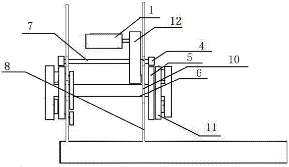
[0019] Embodiment 3 see figure 2 : a power deceleration transmission system of a threading machine, comprising a motor 1, a gear box 12, a gear box output shaft 7, a driving wheel 4, a chuck, and a chuck shaft 6, the motor is connected to the gear box, and the deceleration The box is fixed on the frame, the drive wheel 4 is set and fixed on the output shaft 7 of the reduction box, the chuck shaft 6 is rotated on the frame 8 through the large bearing 10, and the chuck shaft is fixedly installed 6, the second driven wheel 5 and the flat spiral disk 11 are set on it, and the adjacent end faces of the driven wheel 5 and the flat spiral disk 11 are provided with large gaps and convexes, which are used for transmission connection. One is connected with the driving wheel 4, and the flat screw disk 11 cooperates with the brake of the chuck shaft stop system, the chuck is clamped, the chuck shaft brake fails, the chuck shaft rotates, and the power deceleration transmission system comp...


PUM


Abstract

The invention relates to a power deceleration transmission system of a threading machine, comprising a power output wheel, a first driven wheel, a driving wheel and a driven shaft, the power output wheel is fixed on the output shaft of a motor, and the first driven wheel The driving wheel and the driving wheel are fixed on the driven shaft, and the power output wheel is matched with the driven wheel. The driven shaft is arranged on the frame of the threading machine through the bearing, and the chuck shaft is rotated on the frame. A second driven wheel and a plane screw are arranged on the chuck shaft, and the driving wheel is in transmission connection with the second driven wheel or the plane screw. The beneficial effect of the invention is that: the power is provided by the main motor, no power maintenance is required after clamping, the power transmission is all completed by mechanical transmission, and the reliability is high.

Description

technical field [0001] The invention relates to the technical field of threading machines, in particular to a power deceleration transmission system for threading machines. Background technique [0002] At present, the power deceleration transmission system in the threading machine field is only used for threading and pipe cutting operations, which restricts the application of automatic chucks on the threading machine. When the threading machine is loading and unloading, it is necessary to manually hit the chuck , labor-intensive and time-consuming, which restricts the upgrade of the automation of the threading machine. As far as the field of the rotating automatic chuck is concerned, in addition to the main power for the main shaft to run, the equipment also needs auxiliary power to support the automatic chuck. The auxiliary power is divided into Pneumatic and hydraulic, the two kinds of power transmission pipelines are complex, with high leakage and failure, serious power ...

Claims


Application Information

Patent Timeline
Patent Type & Authority Applications(China)
IPC IPC(8): B23G1/44B23Q5/20B23Q7/00
CPCB23G1/44B23Q5/20B23Q7/00B23Q2707/006
Inventor 平春华
Owner SHAOXING JIANHUA METAL LOGISTICS CO LTD
Why Eureka
Try Eureka