Double-layer dust collection device of tabletting machine

A technology of a dust collector and a tablet press, which is applied to presses, material forming presses, manufacturing tools, etc., can solve the problems of difficulty in removing powder, reducing production efficiency, sticking and punching under punching, etc., and achieve uniform gap size. , The effect of powder agglomeration is convenient and easy to operate

Inactive Publication Date: 2011-09-21
上海天和制药机械有限公司
View PDF0 Cites 4 Cited by
  • Summary
  • Abstract
  • Description
  • Claims
  • Application Information

AI Technical Summary

Problems solved by technology

At present, the dust collection device on the market is usually an integral single-layer structure, which is generally made of sheet metal welding. It is difficult to ensure the gap between the suction port and the middle mold table, so the dust suction effect is poor, and it is only suitable for low-speed rotating tablet presses. And it can only absorb the dust on the table surface of the middle mold, and the small amount of powder leaked from the hole of the middle mold cannot be sucked away. The powder leaked from the hole of the middle mold is easy to stick to the surface of the lower punch, which is easy to cause the lower punch to stick. Chong phenomenon
However, the powder on the table top of the middle mold cannot be sucked clean, which may easily cause differences in tablet weight and color mixing when pressing two-color or three-color
At the same time, it is difficult to remove the powder adsorbed in the inner cavity of the dust collection device. After the dust agglomerates, it will block part of the section of the suction channel, reduce the air volume, and greatly reduce the dust collection effect. The operator is required to stop and clean at regular intervals. Punch rod and dust suction device, greatly reducing production efficiency

Method used


Image

  • Double-layer dust collection device of tabletting machine
  • Double-layer dust collection device of tabletting machine
  • Double-layer dust collection device of tabletting machine

Examples


Embodiment Construction

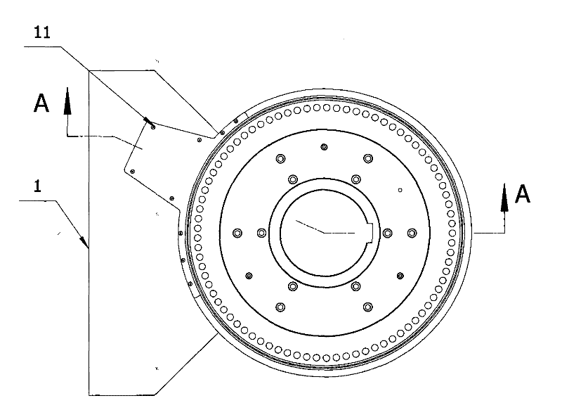
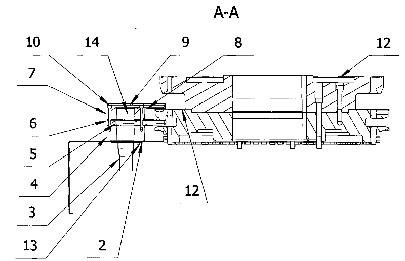
[0020] Figure 1~2 It is a cross-sectional view and a top view of the double-layer dust collection device involved in the present invention. The double-layer vacuum device includes a table cover 1, a gasket 2, a suction pipe joint 3, a lower pad 4, a lower suction plate 5, a lower suction cover 6, an upper pad 7, an upper suction plate 8, Upper suction cover 9, hexagon socket head cap screw 10, countersunk head screw 11, turntable 12, hexagon socket cap screw 13. Among them, the suction pipe joint 3 is installed on the lower surface of the table cover 1, the sealing gasket 2 is installed on the upper surface of the table cover 1, and the lower pad 4 is installed on the top of the sealing gasket 2, and the table cover 1 and the table cover 1 are sealed with socket head cap screws 13. The pad 2, the suction pipe joint 3, and the lower pad 4 are connected and fastened, and then the lower suction plate 5, the lower suction cover 6, the upper pad 7, and the upper powder suction pl...


PUM


Abstract

The invention discloses a double-layer dust collection device of a tabletting machine. The device comprises a dust collection main channel, an upper dust collection opening and a lower dust collection opening, wherein the dust collection main channel is connected with an air collection pipe and is positioned on one side of a rotating platform; the upper dust collection opening is positioned at a middle die hole on the surface of the rotating platform; and the lower dust collection opening is positioned on the surface of a lower plunger rod and comprises a first dust collection inlet and a first auxiliary channel which is connected with the first dust collection inlet and the main channel. In the device, the upper and lower dust collection openings are used for collecting dust on the surface of a middle die platform and the surface of the lower plunger rod respectively. When the dust is accumulated on the surface of the middle die platform, dust collection is performed through the upper dust collection opening; and when the dust leaked from the middle die hole is stuck to the surface of the lower plunger rod, dust collection is performed through the lower dust collection opening so as to achieve an ideal dust collection effect.

Description

technical field [0001] The invention relates to a rotary tablet press, in particular to a double-layer dust suction device for the tablet press. Background technique [0002] In my country's pharmaceutical, chemical, food and other industries, solid powder or granular materials with certain effects are usually compressed into tablets to form tablets or health products. People usually call the machine that is pressed into tablets a rotary tablet press. There is a device on the tablet press that sucks up a small amount of powder that leaks from the bottom of the feeder and the turntable table, called a dust suction device. At present, the dust collection device on the market is usually an integral single-layer structure, which is generally made of sheet metal welding. It is difficult to ensure the gap between the suction port and the middle mold table, so the dust suction effect is poor, and it is only suitable for low-speed rotating tablet presses. And it can only absorb th...

Claims


Application Information

Patent Timeline
Patent Type & Authority Applications(China)
IPC IPC(8): B30B15/00B30B11/00
CPCB30B15/0082B30B11/08
Inventor 赵志能王洪章严学生
Owner 上海天和制药机械有限公司
Why Eureka
Try Eureka