Rotating vane oscillating engine
A swing type, engine technology, applied in the direction of combustion engine, machine/engine, internal combustion piston engine, etc., can solve the problems of low mechanical efficiency, heavy weight, unreasonable engine structure, etc., and achieve the effect of eliminating negative mass and reducing volume
- Summary
- Abstract
- Description
- Claims
- Application Information
AI Technical Summary
Problems solved by technology
Method used
Image


Examples
Embodiment 1
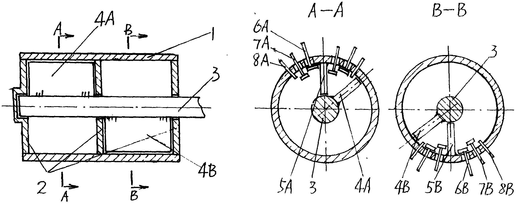
[0013] Embodiment 1: as figure 1 As shown, in the rotary vane swinging engine of the present invention, the two ends of the engine casing 1 are closed by the baffle plate 2, and the rotary vane shaft 3 is arranged inside, and the two ends of the rotary vane shaft 3 are supported on the casing baffle plate 2 and sealed with it. Moving fit, and one end protrudes from the housing baffle plate, the rotor blade shaft 3 is fixedly connected with a rotor blade 4 outward, and the periphery of the rotor blade 4 is respectively sealed and dynamically matched with the inner wall of the engine housing 1 and its baffle plate 2, The engine casing is provided with a partition 5 inwardly, and the periphery of the partition 5 is fixedly connected with the inner wall of the engine casing 1 and its baffle 2 respectively, and is in sealing and dynamic cooperation with the rotor shaft 3. Both sides of the partition 5 are respectively provided with Intake valve 6, exhaust valve 7 and spark plug 8. ...
Embodiment 2
[0020] Embodiment 2: as image 3 As shown, two working cavities A and B of the engine casing 1 are arranged in series, and the two ends of each cavity are closed with baffles 2, and a rotating vane 4A and a partition 5A are arranged in the cavity A, and the two sides of the partition 5A are respectively An intake valve 6A, an exhaust valve 7A and a spark plug 8A are provided. Rotary vanes 4B and partitions 5B are arranged in the chamber B, and intake valves 6B, exhaust valves 7B and spark plugs 8B are respectively arranged on both sides of the partitions 5B. The rotor blade 4A and the rotor blade 4B share the rotor shaft 3 and are connected in series and fixed at 180 degrees to each other. The rotor blade shaft 3 passes through each baffle plate and is sealed and dynamically matched with it. The partition 5A and the partition 5B are 180 degrees to each other. It is provided that the periphery of each partition is fixedly connected with the inner wall of the cavity where it is...
PUM
 Abstract
Description
Claims
Application Information
 - R&D
- Intellectual Property
- Life Sciences
- Materials
- Tech Scout
- Unparalleled Data Quality
- Higher Quality Content
- 60% Fewer Hallucinations
Browse by: Latest US Patents, China's latest patents, Technical Efficacy Thesaurus, Application Domain, Technology Topic, Popular Technical Reports.
© 2025 PatSnap. All rights reserved.Legal|Privacy policy|Modern Slavery Act Transparency Statement|Sitemap|About US| Contact US: help@patsnap.com