
Hydraulic clutch

A hydraulic clutch and clutch technology, applied in clutches, fluid-driven clutches, mechanical-driven clutches, etc., can solve the problems of faster rotation of the main shaft, larger drag torque, and larger shifting noise, and reduce shifting. sound, simplify the oil supply path, and prevent the effect of dragging

Inactive Publication Date: 2011-09-21
HONDA MOTOR CO LTD
View PDF8 Cites 2 Cited by
  • Summary
  • Abstract
  • Description
  • Claims
  • Application Information

AI Technical Summary

Problems solved by technology

[0004] However, in the hydraulic clutch described in the aforementioned Patent Document 1, when the clutch is disengaged, the hydraulic oil in the disengagement side hydraulic chamber is supplied from the oil supply hole formed in the center of the clutch to between the plurality of clutch friction plates and the plurality of clutch discs. , Therefore, when the clutch is disengaged, the amount of oil supplied becomes too much, and the drag torque becomes larger, so that the rotation of the main shaft becomes faster, and the shifting sound during gear shifting becomes louder.

Method used


Image

  • Hydraulic clutch
  • Hydraulic clutch
  • Hydraulic clutch

Examples


Embodiment Construction

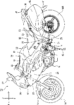
[0053] Hereinafter, an embodiment of the hydraulic clutch of the present invention will be described in detail with reference to the drawings. In addition, the drawings are viewed according to the direction of the reference signs. In the following description, the front and rear, left and right, and up and down are based on the direction observed by the operator. In the figure, the front of the vehicle is referred to as Fr, the rear as Rr, and the left as L , Let the right side be R, the upper side as U, and the lower side as D.

[0054] First, like figure 1 As shown, the body frame 11 of the motorcycle 10 has: a head pipe 12 provided at the front end; a pair of left and right main frames 13 extending backward and downward from the head pipe 12; and a pair of left and right main frames 13 connected to the rear. A pair of left and right pivot plates 14 extending downward.

[0055] In addition, the motorcycle 10 has: a front fork 21 supported on the head pipe 12 in a steerable manne...


PUM


Abstract

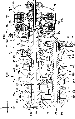
To provide a hydraulic clutch which can prevent a drag of a clutch at the time of disengaging the clutch by decreasing an oil supply quantity between a plurality of clutch plates and a plurality of clutch discs thus decreasing a change hitting sound at the time of shifting. A hydraulic clutch (100) is configured such that the superposition between an oil supply hole (122a, 122b) formed in a clutch pressure plate (102a, 102b) and an oil supply hole (121a, 121b) formed in a clutch center (107a, 107b) becomes maximum when the clutch is engaged.

Description

Technical field [0001] The present invention relates to hydraulic clutches, and more particularly to hydraulic clutches for dual-clutch transmissions. Background technique [0002] As a conventional hydraulic clutch, a dual clutch is known, in which hydraulic first and second clutches which are axially displaced by the supplied hydraulic pressure from the outside and exert a predetermined engagement force are coaxially adjacent to each other. It is configured by arrangement (for example, refer to Patent Document 1). [0003] Patent Document 1: Japanese Patent Application Publication No. 2008-89066 [0004] However, in the hydraulic clutch described in Patent Document 1, when the clutch is disconnected, the hydraulic oil in the hydraulic chamber on the disconnected side is supplied from the oil supply hole formed in the center of the clutch to the clutch plates and the clutch discs. Therefore, when the clutch is disconnected, the amount of oil supply becomes too much, and the drag t...

Claims


Application Information

Patent Timeline
Patent Type & Authority Applications(China)
IPC IPC(8): F16D25/0638
CPCF16D25/10F16D25/123F16D25/0638F16D21/06
Inventor 深谷和幸高桥考作渡边纯也荒井大田中政隆
Owner HONDA MOTOR CO LTD
Learn More