Unmanned aerial vehicle staged autonomous landing method based on visual information fusion

A visual information, drone technology, applied in non-electric variable control, instruments, control/regulation systems, etc., can solve the problem that the safety of the drone at the end of the boat needs to be improved, the drone is difficult to maintain stability, and the camera is lost. Landmark vision and other issues, to achieve the effect of simplifying computational complexity, lowering technical thresholds, and avoiding lag

Active Publication Date: 2018-09-28
SHANGHAI JIAO TONG UNIV
View PDF12 Cites 12 Cited by
  • Summary
  • Abstract
  • Description
  • Claims
  • Application Information

AI Technical Summary

Problems solved by technology

However, it is easy for the camera to lose sight of the landmarks, especially on unmanned boats, where the position of the landmarks is not fixed
In addition, due to the wing-ground effect (the aerodynamic interference generated by the ground to the object when the moving object is running close to the ground), it is difficult for the UAV to maintain stability when it is close to the landing platform of the unmanned boat, so that the success rate of the above method is not high when applied. High, the safety of the final stage of UAV landing needs to be improved

Method used


Image

  • Unmanned aerial vehicle staged autonomous landing method based on visual information fusion
  • Unmanned aerial vehicle staged autonomous landing method based on visual information fusion
  • Unmanned aerial vehicle staged autonomous landing method based on visual information fusion

Examples


Embodiment

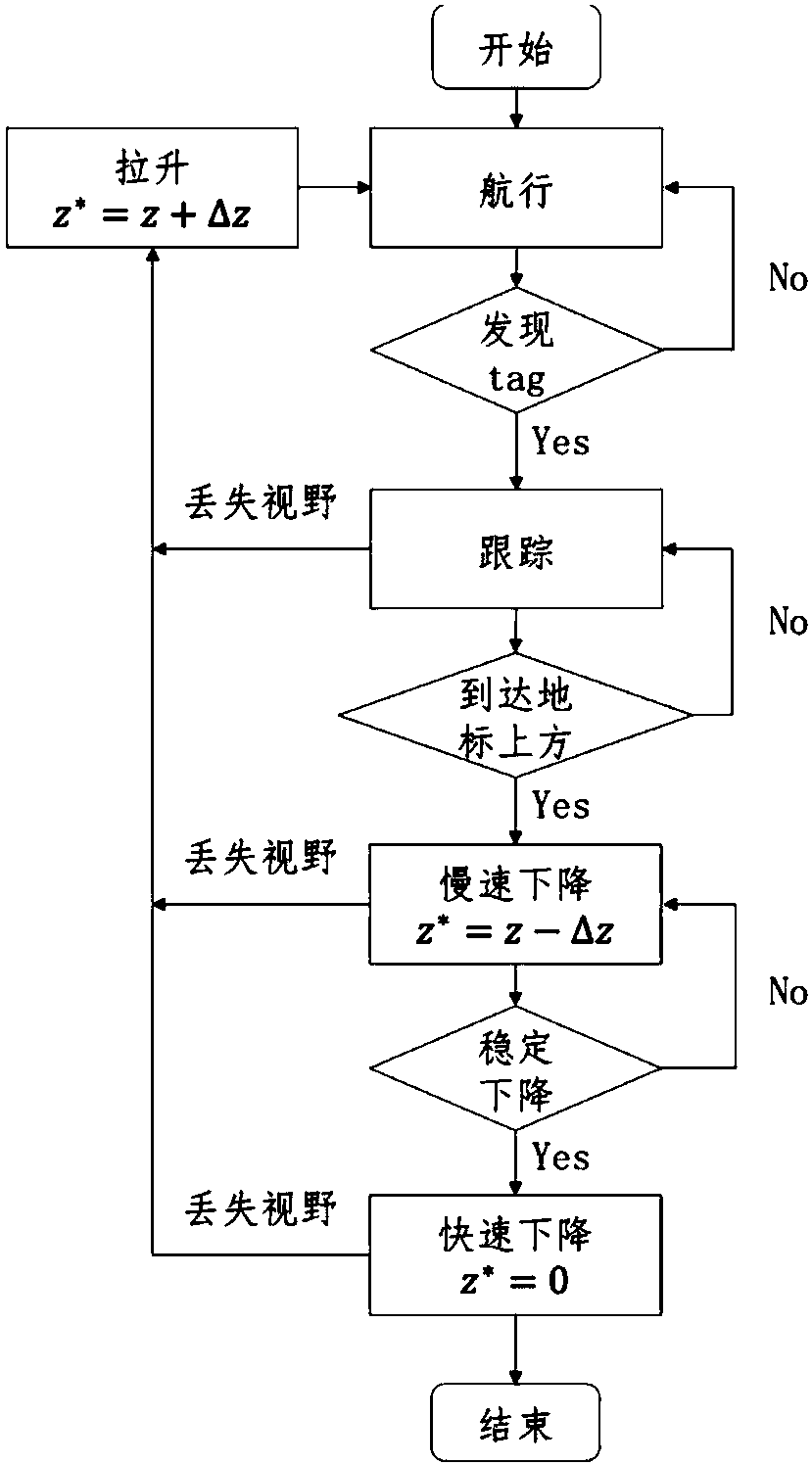
[0063] The following is attached image 3 The technical solution of the present invention is described in detail.

[0064] For the convenience of explanation, the following symbol conventions are first made:

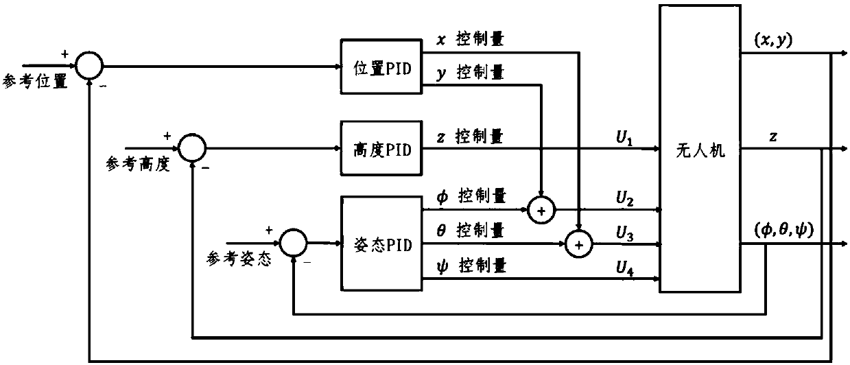
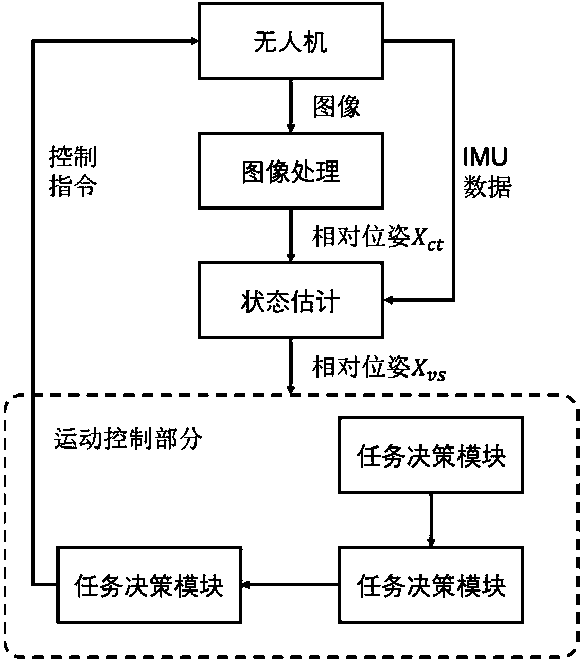
[0065] x ij Refers to the pose of the j reference frame in the i reference frame, where the pose is defined as a 6-dimensional column vector [x y z φθ ψ] T , where (x, y, z) are the position coordinates in the reference system, (φ, θ, ψ) are the angles of rotation around the x-axis, y-axis, and z-axis, respectively, called roll angle, pitch angle, and yaw horn. The reference frames used are: drone reference frame {v}, local reference frame {l}, unmanned boat reference frame {s}, camera reference frame {c}, landmark reference frame {t}. At the same time define some basic symbols of reference frame transformation: if i, j, k represent three reference frames, the symbols Represents the accumulation of transformations, satisfying symbol express The inverse operat...


PUM


Abstract

The invention relates to an unmanned aerial vehicle staged autonomous landing method based on visual information fusion. The method includes the following steps of 1) landmark making: taking a corresponding target landing point on the unmanned ship as a landmark, attaching an AprilTags label to the landmark, and adjusting the angle of the unmanned aerial vehicle camera; 2) image processing: according to the parameter information of the camera and the image information captured by the camera, acquiring the relative pose Xct between the camera and the landmark when the landmark is found; 3) information fusion: performing information fusion on the relative pose Xct between the camera and the landmark and the measurement data of the IMU, and acquiring the real-time relative pose Xvs of the unmanned ship under the unmanned aerial vehicle reference system; 4) motion control: ensuring flight stability and path tracking according to the real-time relative pose Xvs in a nested control mode, atthe same time, landing by adopting a staged landing method. Compared with the prior art, the method has the advantages of being effective and real-time, avoiding lag, and being stable and safe.

Description

technical field [0001] The invention relates to the technical field of intelligent marine robots, in particular to a step-by-step autonomous landing method for unmanned aerial vehicles based on visual information fusion. Background technique [0002] With the advancement of science and technology, unmanned systems are more and more widely used in professional fields such as agriculture, electric power, and ocean. UAV (Unmanned Aerial Vehicle, UAV) is the "darling" of unmanned systems. In recent years, its development speed and application fields have been continuously promoted. [0003] In the marine field, unmanned aerial vehicles with limited battery life but wide search range are usually equipped on unmanned boats with strong battery life but small search range, forming a coordinated formation of aircraft and boats with complementary advantages to complete maritime rescue, environmental For tasks such as monitoring and battlefield reconnaissance, the core technology is t...

Claims


Application Information

Patent Timeline
Patent Type & Authority Applications(China)
IPC IPC(8): G05D1/10
CPCG05D1/101
Inventor 袁野陆宇张卫东姚瑞文胡智焕李茂峰
Owner SHANGHAI JIAO TONG UNIV
Why Eureka
Try Eureka