
Transmission mechanism of cutting machine

A technology of transmission mechanism and cutting machine, which is applied in the direction of transmission device, mechanical equipment, belt/chain/gear, etc. It can solve the problems such as the inability to adjust the width of the cut material and the distance between them, and achieve the effect of cost saving

Inactive Publication Date: 2011-09-21
泗阳浙阳新型保温防水材料有限公司
View PDF5 Cites 0 Cited by
  • Summary
  • Abstract
  • Description
  • Claims
  • Application Information

AI Technical Summary

Problems solved by technology

[0002] Existing cutting machines for processing slabs or marble generally have two fixed cutting knives. The cutting knives are driven by a motor and cut through the cutting teeth on the cutting knives. Because the distance between the two cutting knives is not adjustable, the cutting The width of the material cannot be adjusted. In order to cut a smaller width, it is necessary to add a knife between the two cutting knives

Method used


Image

  • Transmission mechanism of cutting machine
  • Transmission mechanism of cutting machine

Examples


Embodiment Construction

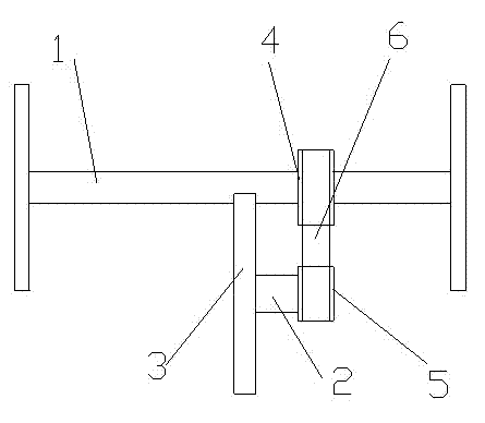
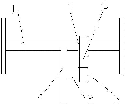
[0010] Below in conjunction with accompanying drawing, the present invention is described in detail, as figure 1 As shown, a cutting machine transmission mechanism includes a driving shaft 1 and a driven shaft 2, two cutting knives 3 are fixedly installed at both ends of the driving shaft, and a cutting knife 3 is also fixedly installed on the driven shaft 2. A driving wheel 4 is fixed on the driving shaft, and a driven wheel 5 is fixed on the driven shaft. Both the driving wheel and the driven wheel can be selected with sprocket or belt pulley, and are transmitted by chain or belt 6.


PUM


Abstract

The invention discloses a transmission mechanism of a cutting machine. The transmission mechanism comprises a driving shaft and two cutters arranged on the driving shaft and is characterized in that a driving wheel is fixedly arranged on the driving shaft; a driven wheel is in transmission connection with the driving wheel; the driven wheel is arranged on a driven shaft; and a cutter is arranged on the driven shaft. Compared with the prior art, the driving wheel and the driven wheel are adopted in the transmission mechanism of the cutting machine for transmission, a motor is not required to drive, so that the cost is saved, synchronous working is realized, the two cutters and the newly-added cutter can synchronously work to cut materials, and the smaller-wide materials are obtained.

Description

technical field [0001] The invention relates to a transmission mechanism for cutting and belongs to the field of cutting machines. Background technique [0002] Existing cutting machines for processing slabs or marble generally have two fixed cutting knives. The cutting knives are driven by a motor and cut through the cutting teeth on the cutting knives. Because the distance between the two cutting knives is not adjustable, the cutting The width of the material cannot be adjusted. In order to cut a smaller width, it is necessary to add a knife between the two cutting knives. Contents of the invention [0003] The technical problem to be solved by the present invention is to provide a cutting machine transmission mechanism with an additional cutting knife in view of the above-mentioned deficiencies in the prior art. [0004] In order to solve the problems of the technologies described above, the technical solution of the present invention is: [0005] A cutting machine tr...

Claims


Application Information

Patent Timeline
IPC IPC(8): F16H7/02F16H7/06
Inventor 赵金法
Owner 泗阳浙阳新型保温防水材料有限公司
Learn More