Ventilating mechanism of transmission

A transmission and air vent technology, which is applied to mechanical equipment, geared components, transmission parts, etc., can solve the problems that oil and air cannot be completely separated, shape, capacity, configuration constraints, etc.

Inactive Publication Date: 2011-09-21
JATCO LTD
View PDF7 Cites 4 Cited by
  • Summary
  • Abstract
  • Description
  • Claims
  • Application Information

AI Technical Summary

Problems solved by technology

[0005] However, even in a transmission with a breather chamber, the oil and air cannot be completely separated, and when the oil reaches the breather hole, it will still be sprayed out from the breather hole
In order to prevent the spraying of oil, it is enough to adjust the shape, capacity and arrangement of the breather chamber to the most appropriate. However, since the breather chamber needs to be arranged in a limited space in the transmission, its shape, capacity, and arrangement are very different. constraints

Method used


Image

  • Ventilating mechanism of transmission
  • Ventilating mechanism of transmission
  • Ventilating mechanism of transmission

Examples


Embodiment Construction

[0027] Hereinafter, embodiments of the present invention will be described with reference to the drawings.

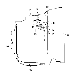
[0028] figure 1 An automatic transmission including the breather mechanism 10 of the present invention is shown. The automatic transmission includes a transmission case 20 , a side cover 30 fastened to the transmission case 20 by bolts, an oil pan 40 , and a shifter case 50 . Shafts, gears, clutches, brakes, and a hydraulic control circuit are arranged in the transmission case 20 , and a torque converter is arranged in the converter case 50 .

[0029] A vent hole 11 for releasing the pressure inside the transmission is formed in an upper portion of the transmission case 20 , and a vent pipe 12 is inserted into the vent hole 11 .

[0030] The transmission case 20 and the converter case 50 are respectively formed with grooves 13, 14 in the vicinity of their joint surfaces, and by making these grooves 13, 14 face each other, a breather chamber 15 is formed throughout the...


PUM


Abstract

The invention discloses a ventilating mechanism of a transmission, which can restrict the oil from being ejected from vents. The ventilating mechanism (10) which releases the pressure in the transmission via the vents comprises a ventilating chamber (15) connected with the vents (11). The ventilating chamber (15) comprises an inner sidewall part (22) which is bent along outer circumferences of gears (31, 32) arranged in the transmission and forms a bent clearance (25) with the outer circumference of the gears (31, 32), and the inner sidewall part (22) is provided with connecting holes (27) extending towards the gears (31, 32) and connecting the ventilating chamber (15) with the clearance (25).

Description

technical field [0001] The present invention relates to a vent mechanism for relieving pressure inside a transmission. Background technique [0002] During operation of the transmission, the pressure inside the transmission increases due to frictional heat, etc. Therefore, in the transmission, a vent hole that communicates the inside of the transmission with the outside of the transmission is provided in the upper part of the transmission, and the pressure inside the transmission is released from the vent hole. [0003] In addition, when the scattered oil or oil in the form of bubbles due to agitation by gears etc. reaches the vent hole, the oil is ejected from the vent hole. Therefore, in the transmission disclosed in Patent Document 1, a breather chamber is provided in front of the breather hole, and oil and air are separated in the breather chamber so that only air is discharged from the breather hole. [0004] Patent Document 1: (Japan) Publication No. 59-81865 [000...

Claims


Application Information

Patent Timeline
Patent Type & Authority Applications(China)
IPC IPC(8): F16H57/02F16H57/027
CPCF16H57/027F16H57/0416
Inventor 杉本雅道
Owner JATCO LTD
Why Eureka
Try Eureka