Combined light emitting diode (LED) lamp structure

An LED lamp and combined technology, applied in the field of lighting, can solve the problems of troublesome installation, increased shelf difficulty, unreasonable structure, etc., and achieve the effect of convenient installation and disassembly, guaranteeing service life, and concise overall structure.

Inactive Publication Date: 2011-09-21
常熟鸿邦新能源有限公司
View PDF7 Cites 4 Cited by
  • Summary
  • Abstract
  • Description
  • Claims
  • Application Information

AI Technical Summary

Problems solved by technology

This patent application scheme has the technical effect described in paragraph 0010 on page 1 of its description, but it has the following shortcomings: First, because the structure of the top cover radiator claimed in the patent application is highly independent, it cannot be connected with adjacent and structural radiators. The friendly connection of the same LED lamps constitutes a certain restriction to the actual use, because in places such as offices, shopping malls, schools, parking lots, cultural and entertainment venues, exhibition venues, sports venues and even homes, it is usually necessary to combine two or more LED lamps. The lamps are installed in a random combination; the second is that the structure of the lampshade and the shelf used to configure the lampshade is unreasonable. As far as the shelf is concerned, not only the assemblability with th

Method used


Image

  • Combined light emitting diode (LED) lamp structure
  • Combined light emitting diode (LED) lamp structure
  • Combined light emitting diode (LED) lamp structure

Examples


Example Embodiment

[0027] Example 1:

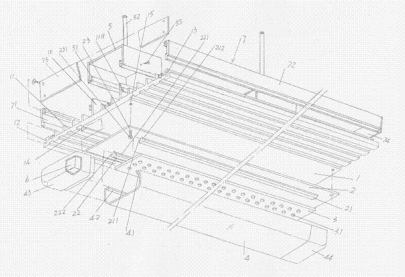
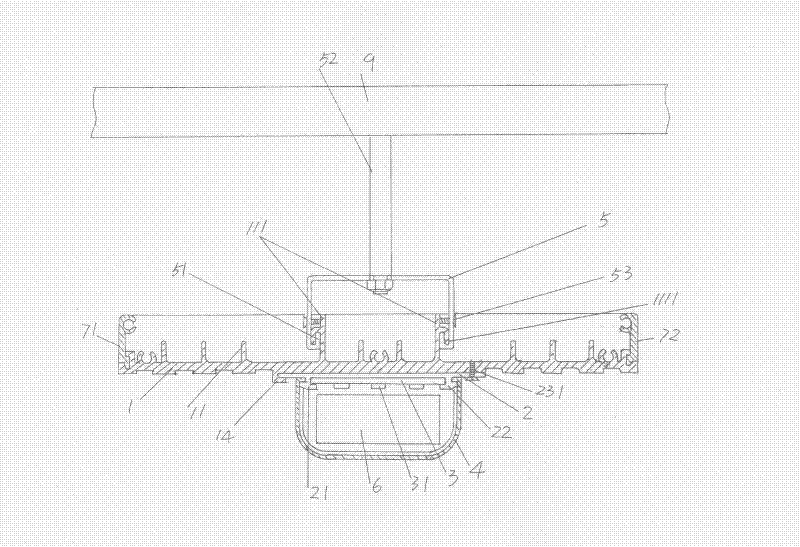
[0028] please see figure 1 and figure 2 ,because figure 1 and figure 2 and even Figure 3 to Figure 9 The position state shown is the state of the LED lamps provided by the present invention in use, so in the following descriptions, the orientation (directionality) concepts of facing upward, downward, left and right are all based on the diagram The location status of , for example.

[0029] Depend on figure 1 As shown, on the surface of the heat dissipation substrate 1 facing upward and along the length direction of the heat dissipation substrate 1 (the length direction refers to the direction from left to right of the heat dissipation substrate 1), there are protrusions on the surface of the heat dissipation substrate 1 at intervals. A group of cooling fins 11, in which there is a pair of fixed bracket inserting fins 111 that not only have the function of cooling fins but also can be inserted into the fixing bracket 5 mentioned below , the pair o...

Example Embodiment

[0036] Example 2:

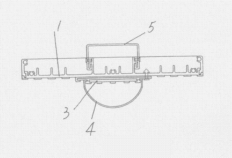
[0037] please see image 3 , only the cross-sectional shape of the photomask 4 is changed to a spherical crown shape, and the rest are the same as the description of embodiment 1.

Example Embodiment

[0038] Example 3:

[0039] please see Figure 4 , only the cross-sectional shape of the photomask 4 is changed to a heart shape, also called a heart shape, and the rest are the same as the description of embodiment 1.


PUM


Abstract

The invention discloses a combined light emitting diode (LED) lamp structure, and belongs to the technical field of illumination. The combined LED lamp structure comprises a radiating substrate, a group of radiating fins, an LED substrate fixing connector, an LED substrate, a photomask and one or more fixed brackets, wherein the group of radiating fins protrudes the surface of the radiating substrate and comprises a pair of fixed bracket inserted fins, a first tabling groove is formed on the side edge of one side of the radiating substrate, and a second tabling groove is formed on the side edge of the other side of the radiating substrate; the LED substrate fixing connector is connected with one side of the radiating substrate and positioned at the middle part of the radiating substrate, and first and second conducting bars parallel to each other are formed on the LED substrate fixing connector; the LED substrate is inserted between the first and second conducting bars, and a plurality of LED light sources are arranged on the LED substrate; the photomask is glidingly matched with the first and second conducting bars, and the LED light sources face the photomask; and the one or more fixed brackets are tabled and matched with the pair of fixed bracket inserted fins. The combined LED lamp structure has the advantages of ensuring the service lives of the LED light sources, meeting the illumination requirements of different occasions and the diverse requirements of shapes, along with convenience for assembly, disassembly and manufacturing.

Description

technical field [0001] The invention belongs to the technical field of lighting, and in particular relates to a combined LED lamp structure. Background technique [0002] Due to the characteristics of high luminous efficiency, energy saving, green environmental protection and long service life, LED lights are favored by people. There is no lack of technical information about LED lights in published Chinese patent documents. For example, CN201748219U recommends a For example, CN201757302U introduces an assembled LED lamp, and CN201772302U provides an LED lamp, and so on. [0003] A typical technical solution, such as the LED lamp provided by the invention patent application publication number CN101984280A, consists of a shelf, a lampshade, a reflective panel, an LED light source module, a top cover radiator and a light pole. The lampshade is placed on the shelf, and the reflective panel and LED The light source module is matched and placed between the lampshade and the top c...

Claims


Application Information

Patent Timeline
IPC IPC(8): F21S2/00F21V29/00F21V19/00F21V17/10F21Y101/02F21S8/00F21V29/50F21V29/74F21Y115/10
Inventor 邱柏东
Owner 常熟鸿邦新能源有限公司
Why Eureka
Try Eureka