AI technical title is built by PatSnap AI team. It summarizes the technical point description of the patent document.
A root cause alarm and device technology, applied in digital transmission systems, electrical components, transmission systems, etc., can solve problems such as large network resources and error-prone, and achieve the effect of narrowing the detection range
Active Publication Date: 2011-09-21
NEW H3C TECH CO LTD
View PDF3 Cites 17 Cited by
Summary
Abstract
Description
Claims
Application Information
AI Technical Summary
This helps you quickly interpret patents by identifying the three key elements:
Problems solved by technology
Method used
Benefits of technology
Problems solved by technology
It can be seen that using the existing alarm correlationanalysis method to detect root alarms is error-prone and takes up a lot of network resources
Method used
Image
Click on the blue label to locate the original text in one second.
Reading with bidirectional positioning of images and text.
Examples
Embodiment 1
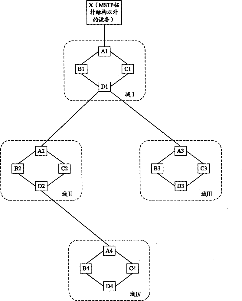
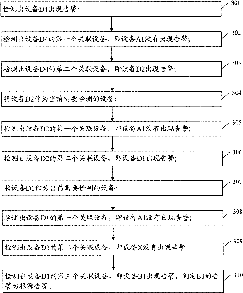
[0053] like image 3 It is a flow chart of a method for detecting root cause alarms based on MSTP topology according to an embodiment of the present invention. In this example, figure 1 The shown device D4 has an alarm. It is assumed that the root alarm of the alarm is the alarm of the device B1. The steps of detecting the root alarm in this embodiment include:
[0054] Step 301: Detecting that an alarm occurs on the device D4. The associated device information of D4 is: D4 {[NA, A1, 0, D2]; [IV, A4, 1, B4]; [IV, A4, 2, C4]}, that is, the associated device of device D4 is represented by From upstream to downstream are A1, D2, A4, B4, and C4 in turn, and then detect whether there is an alarm in each associated device in turn.
[0055] Step 302: Detect whether the first associated device of D4, i.e., the device A1, has an alarm. It has been explained above that the present invention only detects the root cause alarm located inside the MSTP topology. Therefore, as the total do...
Embodiment 2
[0068] like Figure 4 It is a flowchart of a method for detecting root cause alarms based on MSTP topology in Embodiment 2 of the present invention. In this example, figure 1 The shown device D4 has an alarm, assuming that the alarm itself is the root alarm, and the steps for detecting the root alarm in this embodiment include:
[0069] Step 401: Detecting that an alarm occurs on the device D4. The associated device information of D4 is: D4 {[NA, A1, 0, D2]; [IV, A4, 1, B4]; [IV, A4, 2, C4]}, that is, the associated device of device D4 is represented by From upstream to downstream are A1, D2, A4, B4, and C4 in turn, and then detect whether there is an alarm in each associated device in turn.
[0070] Step 402: Detect whether the first associated device of D4, that is, device.A1, has an alarm. It is the same as the case of step 302 in the first embodiment above. The detection result of A1 is that there is no alarm, and proceed to step 403. Of course, step 403 may also be di...
PUM
Abstract
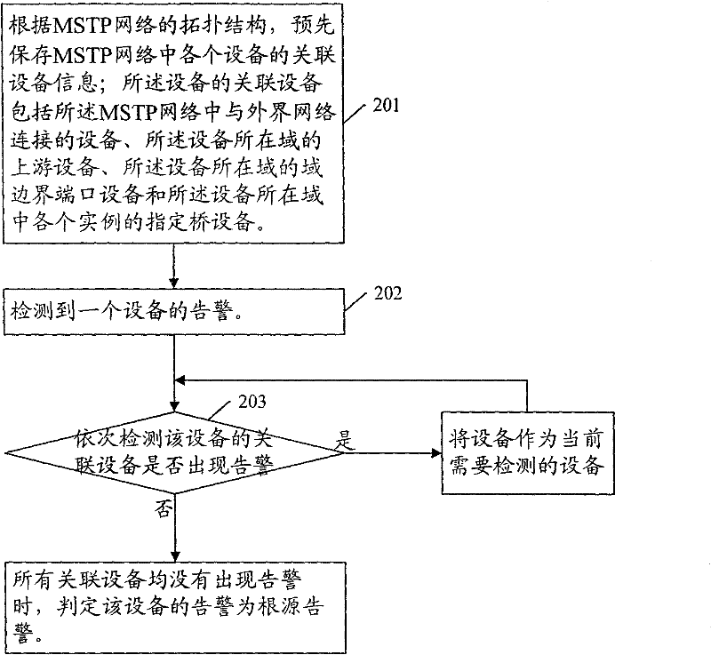
The invention provides a method and a device for detecting root alarm. The method comprises the following steps: (A) pre-storing associated equipment information of each equipment in an MSTP (Multiple Spanning Tree Protocol) network according to the topological structure of the MSTP network, the associated equipments including total domain boundary port equipment, total designated bridge equipment, domain boundary port equipment and designated bridge equipment; (B) executing the step (C) when an alarm is detected from equipment; and (C) sequentially detecting whether each associated equipment of the equipment sends an alarm according to the associated equipment information of the equipment, if so, further executing the step (C) by using the associated equipment as the equipment to be detected, otherwise, detecting the next associated equipment until determining that every associated equipment does not send the alarm, and determining that the alarm of the equipment is the root alarm. The method provided by the invention can accurately and efficiently detect the root alarm in the network.
Description
technical field [0001] The invention relates to the technical field of alarm association analysis, in particular to a method and equipment for detecting root alarms. Background technique [0002] With the rapid expansion of the network scale and the rapid growth of IT business volume, the number of alarms reported by network devices to the network management has also increased sharply. Among these alarms, some are root alarms, and some are symptom alarms. One root alarm usually corresponds to multiple symptom alarms. For example, for multiple network devices with upstream and downstream connections in the network topology, when an upstream device fails, it will cause all downstream devices with only a unique link to fail; in this case, the alarm generated by the upstream device failure It is the root cause alarm, and the alarm generated by the failure of the downstream equipment is the appearance alarm. If the root cause alarm is accurately detected, the faulty upstream de...
Claims
Application Information
Patent Timeline
Application Date:The date an application was filed.
Publication Date:The date a patent or application was officially published.
First Publication Date:The earliest publication date of a patent with the same application number.
Issue Date:Publication date of the patent grant document.
PCT Entry Date:The Entry date of PCT National Phase.
Estimated Expiry Date:The statutory expiry date of a patent right according to the Patent Law, and it is the longest term of protection that the patent right can achieve without the termination of the patent right due to other reasons(Term extension factor has been taken into account ).
Invalid Date:Actual expiry date is based on effective date or publication date of legal transaction data of invalid patent.

