
Mounting structure for an air-fuel ratio sensor in a motorcycle, and exhaust subassembly including same

a technology of air-fuel ratio and mounting structure, which is applied in the direction of cycle equipment, machines/engines, cycles, etc., can solve the problems of significant influence on the detection accuracy and the inability to linearly detect oxygen concentration over a wide range of values, so as to reduce the amount of inward projection of air-fuel ratio sensors and improve the efficiency of catalytic converters , the effect of reducing the amount of inward projection

Active Publication Date: 2009-11-03
HONDA MOTOR CO LTD
View PDF20 Cites 21 Cited by
  • Summary
  • Abstract
  • Description
  • Claims
  • Application Information

AI Technical Summary

Benefits of technology

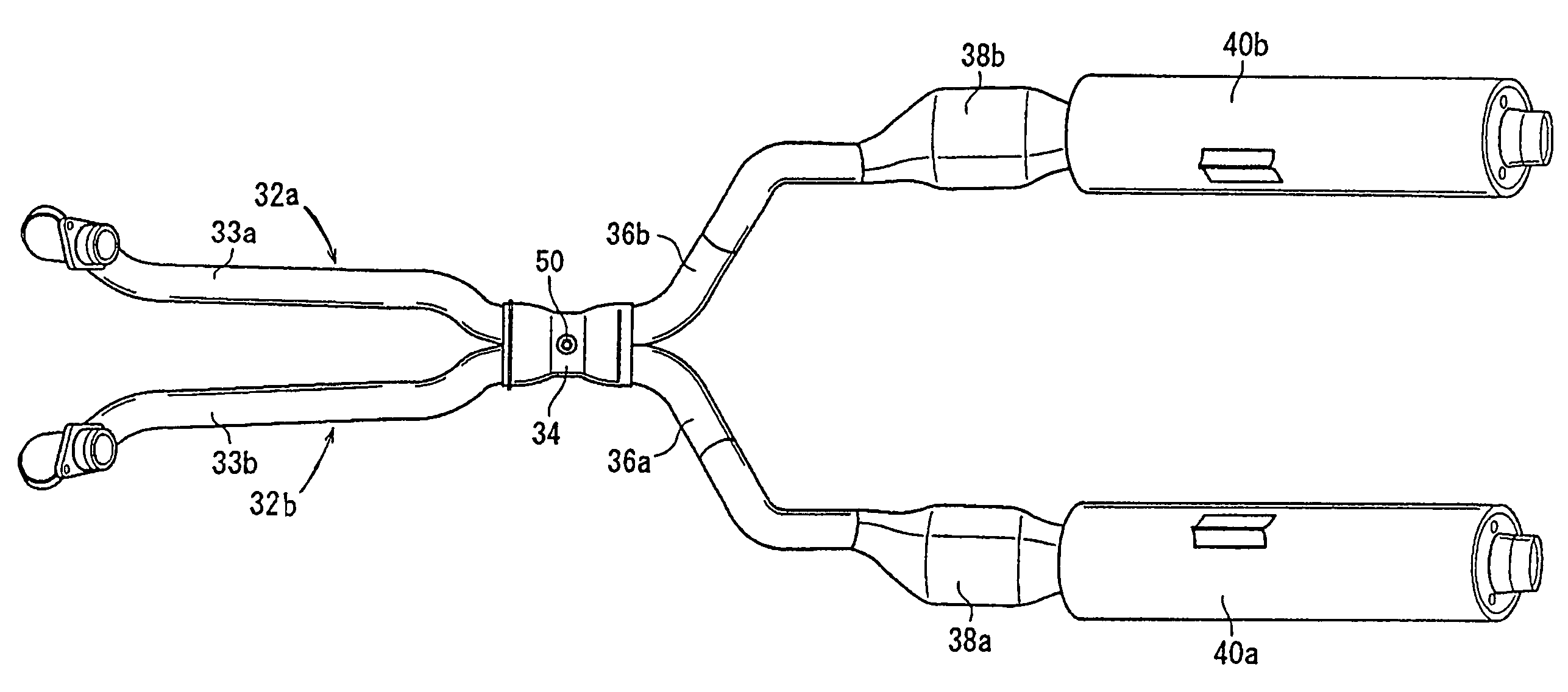
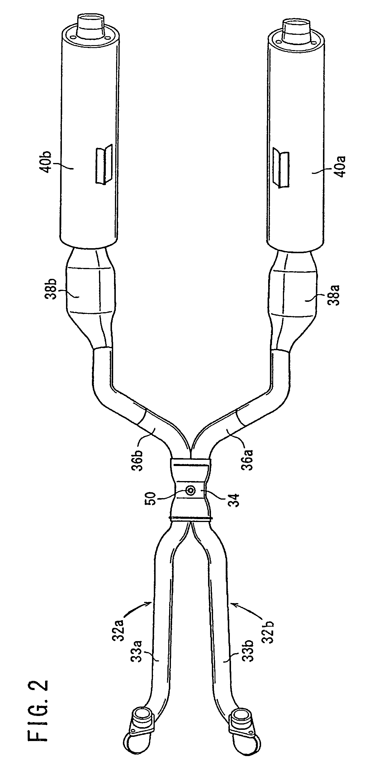
The present invention provides a mounting structure for an air-fuel ratio sensor in a motorcycle with a multi-cylinder engine. The sensor is mounted on at least one of the exhaust pipes connected to the engine cylinders. This arrangement allows for the detection of the concentration of oxygen in the exhaust gas of the motorcycle. By using a minimum number of air-fuel ratio sensors, the concentration of oxygen can be efficiently and accurately detected, and air-fuel ratio control can be performed to improve combustion efficiency and promote the effectiveness of catalytic converters. The mounting structure reduces the amount of inward projection of the air-fuel ratio sensor, providing adequate space for the flow of exhaust gas. Overall, the invention provides a reliable and effective solution for detecting and controlling the air-fuel ratio in multi-cylinder engines.

Problems solved by technology

This kind of oxygen sensor determines whether the air-fuel ratio is rich or lean with respect to a stoichiometric air-fuel ratio in a narrow region near the stoichiometric air-fuel ratio, but it is not suitable for linear detection of the oxygen concentration over a wide range of values.
However, since the air-fuel ratio sensor detects the oxygen concentration over a wide range rather than in a narrow region near the stoichiometric air-fuel ratio as mentioned above, the detection accuracy of the air-fuel ratio sensor may be affected significantly by the location of the air-fuel ratio sensor.

Method used


Image

  • Mounting structure for an air-fuel ratio sensor in a motorcycle, and exhaust subassembly including same
  • Mounting structure for an air-fuel ratio sensor in a motorcycle, and exhaust subassembly including same
  • Mounting structure for an air-fuel ratio sensor in a motorcycle, and exhaust subassembly including same

Examples


Embodiment Construction

[0022]A number of selected illustrative embodiments of the mounting structure of the air-fuel ratio sensor in the motorcycle according to the present invention will now be described in detail with reference to FIGS. 1 to 7. These embodiments are intended to illustrate, rather than to limit the invention. It should be understood that only structures considered necessary for clarifying the present invention are described herein. Other conventional structures, and those of ancillary and auxiliary components of the system, are assumed to be known and understood by those skilled in the art.

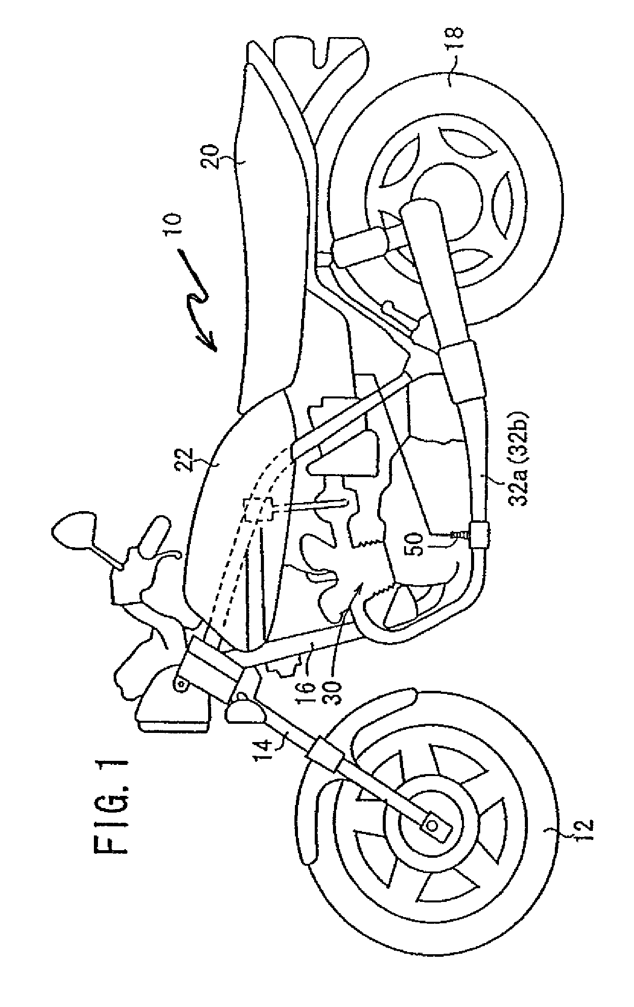
[0023]FIG. 1 is a simplified side plan view of a motorcycle 10 having an air-fuel ratio sensor 50, according to a first illustrative embodiment of the present invention, mounted on a convergent connector located medially in the exhaust system, at a junction between two exhaust pipes. The motorcycle 10 itself has a known structure. More specifically, a front wheel 12 is supported to a front fork 14. The...


PUM


Abstract

A mounting structure is provided for an air-fuel ratio sensor on an exhaust pipe in a motorcycle in which a concentration of oxygen in an exhaust gas can be detected efficiently and accurately by the air-fuel ratio sensor. The air-fuel ratio sensor is mounted on a convergent connector of exhaust pipes, which, in turn, are operatively connected to the cylinders of a multi-cylinder engine. The air-fuel ratio sensor is located upstream of catalytic converters provided in the exhaust pipes, and may be mounted so as to be oriented substantially vertically when the motorcycle is in an upright configuration, or alternatively, may be inclined toward the rear of the motorcycle.

Description

CROSS-REFERENCE TO RELATED APPLICATIONS[0001]The present invention claims priority under 35 USC 119 based on Japanese patent application No. 2004-286063, filed on Sep. 30, 2004. The subject matter of this priority document is incorporated by reference herein.BACKGROUND OF THE INVENTION[0002]1. Field of the Invention[0003]The present invention relates to an air-fuel ratio sensor, to a structure for mounting the sensor to an exhaust system component of a motorcycle, and to an exhaust subassembly incorporating the sensor. More particularly, the present invention relates to a mounting structure for affixing an air-fuel ratio sensor to an exhaust pipe in a motorcycle, and to a related exhaust subassembly including the sensor, the mounting structure, and the exhaust pipe.[0004]2. Background Art[0005]It is well known to employ an oxygen sensor in a motorcycle exhaust system, so as to improve the catalytic efficiency thereof. In a motorcycle having a multi-cylinder engine, such an oxygen se...

Claims


Application Information

Patent Timeline
Patent Type & Authority Patents(United States)
IPC IPC(8): F01N3/00B62J99/00B62M7/02F01N13/00F01N99/00F02D35/00
CPCB62J99/00F01N13/008F01N13/011F02B61/02F02B77/086F01N13/009F01N13/107B62J2099/002B62K2207/00F01N2560/025B62J45/42B62J45/41
Inventor KONO, TOMOYAABE, TAKERUYAMAZAKI, RYUTAROURAKI, MAMORU
Owner HONDA MOTOR CO LTD
Learn More