Eureka AIR delivers breakthrough ideas for toughest innovation challenges, trusted by R&D personnel around the world.

A multi-stage gear transmission system used in a stepping washing machine and the washing machine

A gear transmission and washing machine technology, applied in the field of washing machines, can solve the problems of affecting the concentricity of the shaft, uneven force on the feet, user fatigue, etc., to save production and installation costs, simplify the clutch transmission structure, and achieve high meshing stability. Effect

Active Publication Date: 2016-08-10
QINGDAO HAIER WASHING MASCH CO LTD
View PDF9 Cites 0 Cited by
  • Summary
  • Abstract
  • Description
  • Claims
  • Application Information

AI Technical Summary

Problems solved by technology

Since the foot pedal is stepped on with one foot, the following problems inevitably occur during use: 1. When the foot pedal of the sports washing machine is stepped on with one foot, the force on the user's feet is uneven, which may easily cause user fatigue and reduce the load of the washing machine. Performance; 2. There is only one pedal and the pedals are generally designed off-axis. During the operation of the washing machine, it will inevitably cause asymmetrical force on the washing machine, which will affect the concentricity of the shaft and affect the vibration and vibration of the washing machine. Noise has a negative impact, etc.
[0009] The existing double-pedal scheme has a complex structure, and generally uses planetary gear transmission, and the output shaft and gear move up and down to realize the conversion of the washing and dehydration process, resulting in low reliability of the washing machine and restricting large-scale industrial production

Method used


Image

  • A multi-stage gear transmission system used in a stepping washing machine and the washing machine
  • A multi-stage gear transmission system used in a stepping washing machine and the washing machine
  • A multi-stage gear transmission system used in a stepping washing machine and the washing machine

Examples


Embodiment 1

[0042] Such as Figure 4 As shown, the second one-way bearing 84 and the third one-way bearing 85 described in this embodiment are arranged in the lower bevel tooth 82 in the upper and lower order, and the groove segments are two, respectively the upper groove segment 40 and the lower groove section 41 are arranged on the output shaft 4 in the order of up and down, and the distance between them satisfies: when washing, the output shaft 4 moves upward, only the first one-way bearing 83 is located in the upper groove section 40, and the upper bevel gear 81 Lost function, the second one-way bearing 84 and the third one-way bearing 85 act together on the output shaft 4, when the transmission mechanism drives the upper and lower bevel gears 81, 82 to rotate forward and reverse, the upper bevel gear 81 rotates but does not act on the output shaft 4, And lower bevel gear 82 drives output shaft 4 forward and reverse to realize washing; The third one-way bearing 85 works together. The...

Embodiment 2

[0044] Such as Figure 5 As shown, the difference between this embodiment and the above-mentioned embodiment is that the upper and lower groove segments are combined into one groove segment 42, and the length of the groove segment 42 is between the first one-way bearing 83 and the third one-way bearing 85. The length of the distance between them satisfies: when washing, the output shaft 4 moves upward, only the first one-way bearing 83 is located in the groove section 42, the upper bevel gear 81 loses its function, the second one-way bearing 84 and the third one-way bearing 85 Work together on the output shaft 4, when the transmission mechanism drives the upper and lower bevel gears 81, 82 to rotate forward and reverse, the upper bevel gear 81 rotates but does not act on the output shaft 4, while the lower bevel gear 82 drives the output shaft 4 forward and reverse to realize washing; dehydration , the output shaft 4 moves downward. At this time, only the second one-way bearin...

Embodiment 3

[0046] Such as Figure 6 and Figure 7 As shown, the difference between this embodiment and the above two embodiments is that the installation order of the second one-way bearing 84 and the third one-way bearing 85 is reversed, and the third one-way bearing 85 is above the second one-way bearing 84, and the A groove segment 43 is provided on the output shaft of the motor, and the length of the groove segment 43 satisfies: when washing, the output shaft 4 moves upwards, only the third one-way bearing 85 is located in the groove segment 43, and the first one-way bearing 83 and The second one-way bearing 84 works together on the output shaft 4. Since the first one-way bearing 83 and the second one-way bearing 84 act oppositely, when the transmission mechanism drives the upper and lower bevel teeth 81 and 82 to rotate forward and backward, the upper and lower bevel teeth Teeth 81, 82 drive the output shaft to reverse to realize washing; during dehydration, the output shaft 4 move...


PUM


Abstract

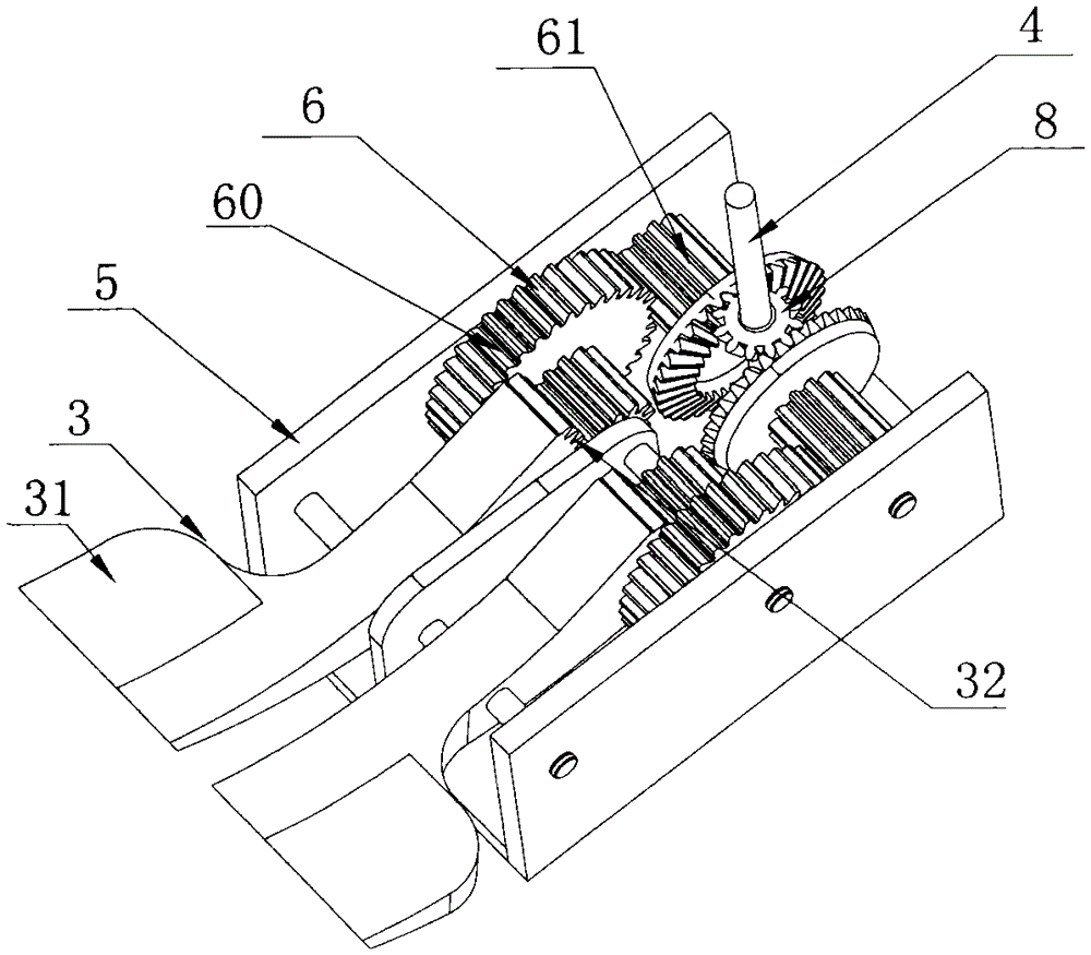
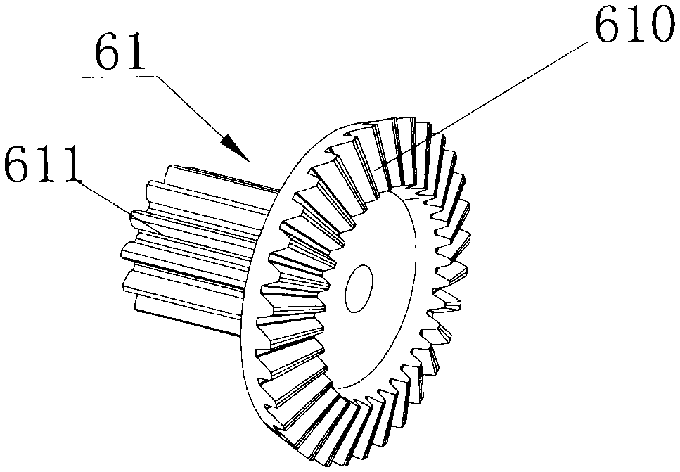
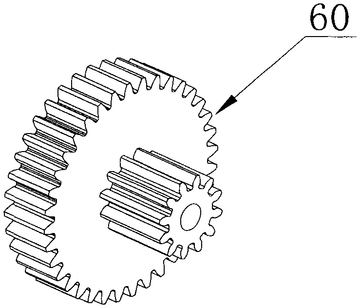
The invention discloses a multi-stage gear transmission system for a stepping washing machine and the washing machine. The transmission system includes a base, an output shaft, a transmission mechanism for transmitting power to the output shaft, a clutch structure for realizing washing and dehydration, and a pivot fixing There are two pedals on the base to provide power. The output shaft can go up and down in the axial direction and cooperate with the clutch structure to realize the clutch of washing and dehydration. The clutch structure includes output bevel gears and one-way Bearings, the transmission mechanism is two groups, and each group corresponds to a foot pedal, including at least two sets of double gears for meshing transmission. One end of the foot pedal is a pedal, and the end of the other end is a section of arc-shaped rack. One of the double gears meshes with the arc-shaped rack for transmission, the other double gear meshes for transmission with the output bevel gear, and the two gears mesh for transmission to form a transmission composed of pedal arc-shaped racks, double gears and output bevel teeth. chain. The invention has the advantages of simple structure, uniform stress and high reliability.

Description

technical field [0001] The invention relates to a washing machine, in particular to a washing machine and a transmission system, in particular to a double-pedal washing machine and a multi-stage gear transmission system. Background technique [0002] Ordinary washing machines use electric energy to drive motors, such as fully automatic washing machines. The motor drives the pulsator or inner tub to perform washing or dehydration work, but the process of washing and dehydration is switched by a complex clutch device such as a deceleration clutch, and the process is complicated. , high cost; in addition, such as a double-tub washing machine, the pulsator and the centrifugal dehydration bucket are driven by two motors respectively to realize the functions of washing and drying, and the washing and dehydration process is also realized by electric power and two barrels; another The mop washing and drying device can be used for washing and drying in one set, but it cannot be switc...

Claims


Application Information

Patent Timeline
Patent Type & Authority Patents(China)
IPC IPC(8): D06F37/40A63B22/04
Inventor 杨明旭许升刘杰
Owner QINGDAO HAIER WASHING MASCH CO LTD
Why Eureka
Eureka Blog
Learn More