Truss string structure

A beam structure and component technology, applied in the field of suspension beam structure, can solve the problem of uneven stress of suspension beam structure, and achieve the effect of uniform force

Active Publication Date: 2011-09-28
CCDI INT SHENZHEN DESIGN CONSULTANTS
View PDF4 Cites 12 Cited by
  • Summary
  • Abstract
  • Description
  • Claims
  • Application Information

AI Technical Summary

Problems solved by technology

[0004] Embodiments of the present invention provide a suspension beam structure, wh

Method used


Image

  • Truss string structure
  • Truss string structure
  • Truss string structure

Examples


Embodiment 1

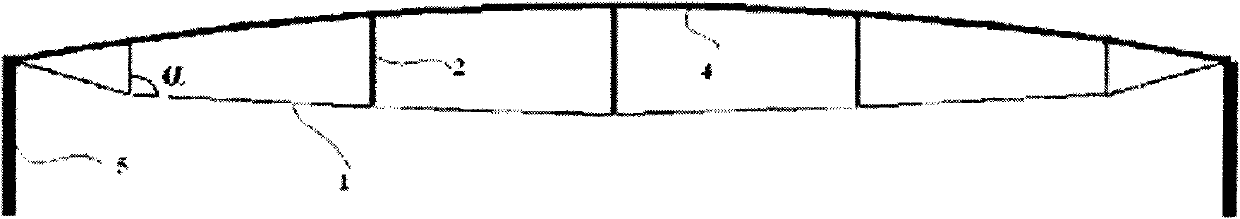
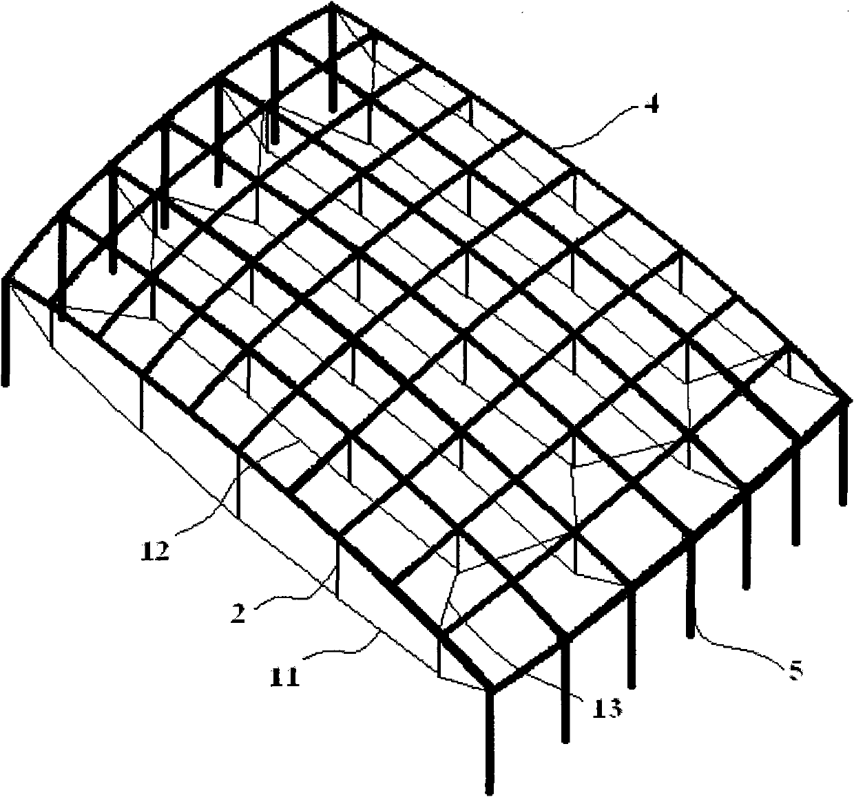
[0042] Embodiments of the present invention provide a suspensive beam structure, such as Figure 2 to Figure 5 As shown, it includes a grid beam 4 on the upper part and a chord structure connected to the lower part of the grid beam 4 .

[0043] The grid beam 4 is preferably a single-layer grid beam, such as a two-way orthogonal vertically placed continuous grid beam, and its two ends are used to be connected to vertical members 5 such as columns and walls, or to be connected to horizontal members. The member should have a large lateral stiffness to ensure that it can bear the tension exerted by the cable.

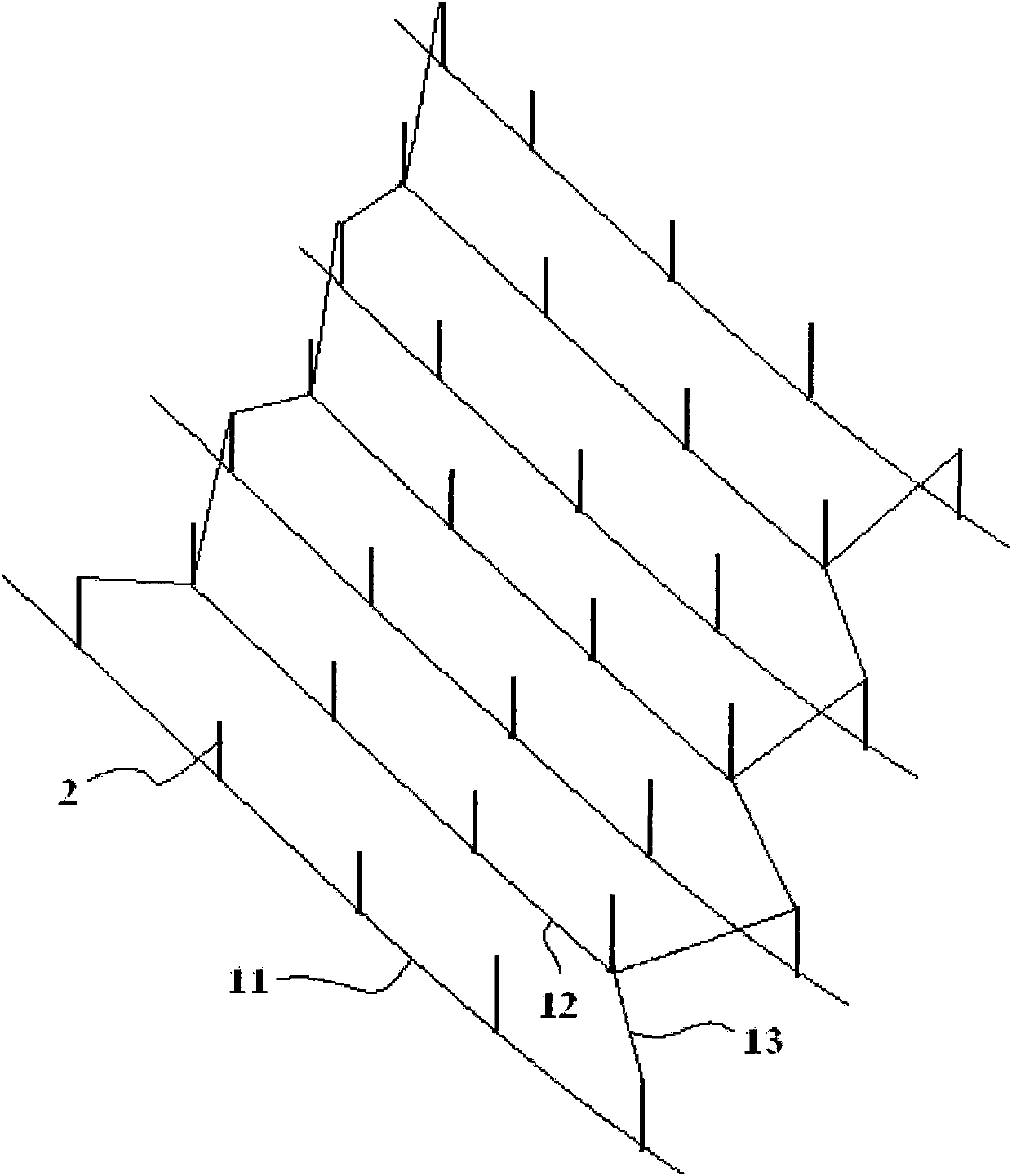
[0044] The suspensive structure includes a plurality of main cables 11 extending from one end of the grid beam 4 to the other and distributed side by side. connected, or connected with the horizontal member), and the projection of each main cable 11 on the horizontal plane is parallel to the first direction, and the first direction is preferably parallel to the length dire...

Embodiment 2

[0052] An embodiment of the present invention provides a suspension beam structure, which is similar to the suspension beam structure in Embodiment 1. The difference is that the suspensive beam structure of this embodiment also includes a plurality of cable-stayed members 3, which can be cable-stayed rods (such as cable-stayed bar steel) or cable-stayed cables (such as cable-stayed steel cables), the lower end of which is Connect the lower end node of a strut 2 (that is, the position where the strut 2 is connected to the main cable 11 or the secondary cable 12), and the upper end is connected to the upper node of another strut 2 (that is, the strut 2 and the grid beam 4 connected position), and the projection of the included angle between the cable-stayed member 3 and the main cable 11 and the secondary cable 12 on the horizontal plane is greater than 0 degrees and less than 90 degrees, that is to say, the cable-stayed member 3 is relatively Cable 12 is arranged obliquely.

...


PUM


Abstract

Relating to the field of engineering design, the invention provides a truss string structure which can provide a solution to the problem of uneven distribution of stress existing in present truss string structures. In the truss string structure provided in the invention, a grid beam is connected to vertical members or horizontal members; the lower ends of struts are in connection with main cables or secondary cables, and the upper ends are in connection with the grid beam; projections of the main cables on a horizontal surface are in parallel with a first direction, and each main cable is connected to at least two struts, and the main cable ends are connected to the grid beam ends or the vertical member top or the horizontal member; projections of the secondary cables on a horizontal surface are in parallel with the first direction, and the two ends of each secondary cable are connected to at least one strut respectively, with the connected parts between a secondary cable and two struts also in connection with the lower ends of two inclined cables respectively, and the upper ends of the inclined cables are connected to the grid beam or the vertical member tops or the horizontal members; on a horizontal surface, projections of angles between the inclined cables and the secondary cables are greater than 90 degrees and less than 180 degrees. Thus, the truss string structure of the invention can be used in large-span space structures.

Description

technical field [0001] The invention relates to the field of structural engineering design, in particular to a string beam structure. Background technique [0002] Suspension beam (string truss) structure is a commonly used semi-rigid structural system, which mainly includes beams (trusses), cables, struts, and vertical members; The ends are connected to beams (trusses) and together they are connected to vertical members. The struts (the struts are preferably arranged in the vertical direction) are arranged in the plane of the cables and beams (trusses) along the length direction of the cables, so as to form a structural whole. Applying the initial pre-tension force through the cable can make the strut generate upward pressure on the beam (truss), so that the beam (truss) produces an upward arch deformation; The deformation can fully or partially offset the deflection deformation caused by the applied gravity load, so that the actual deformation of the beam (truss) caused ...

Claims


Application Information

Patent Timeline
IPC IPC(8): E04C3/02
Inventor 傅学怡杨想兵高颖
Owner CCDI INT SHENZHEN DESIGN CONSULTANTS
Why Eureka
Try Eureka