Method for realizing integration of polarizing beam splitter and slow light device by using bend waveguide

A polarized beam splitter and technology for its implementation, which are applied in the coupling of optical waveguides, optical elements, light guides, etc., can solve the problems of integrating polarized beam splitters and slow light devices on the same plate, and reduce the The effect of production difficulty, low power consumption and low loss

Inactive Publication Date: 2011-09-28
BEIJING UNIV OF POSTS & TELECOMM
View PDF4 Cites 19 Cited by
  • Summary
  • Abstract
  • Description
  • Claims
  • Application Information

AI Technical Summary

Problems solved by technology

However, the integration research mentioned above did not integrate th

Method used


Image

  • Method for realizing integration of polarizing beam splitter and slow light device by using bend waveguide
  • Method for realizing integration of polarizing beam splitter and slow light device by using bend waveguide
  • Method for realizing integration of polarizing beam splitter and slow light device by using bend waveguide

Examples


Embodiment Construction

[0035] Realization of Photonic Crystal Polarizing Beam Splitter

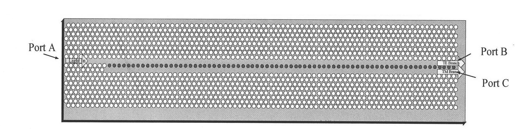
[0036] The structure of PBS is as follows figure 1 As shown, it contains two W1 waveguides, and a row of air holes is separated between the two waveguides. The value of lattice constant a=459.25nm, the radius of ordinary air holes r=165.33nm, the refractive index of background GaAlAs n=3.32, the radius of red air holes rr=137.78nm=0.3a. Port A is the entrance, TE light is output from Port B along the TE branch, and TM light is coupled into the TM branch after the coupling length L and then output from Port C. The formula for calculating the coupling length is as follows:

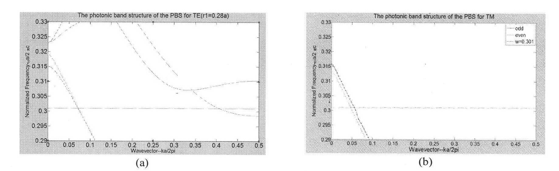
[0037] L = 2 π | k even - k odd |

[0038] Such as figure 2 As shown in (a), the odd mode (odd) and the even mode (even) of ...


PUM


Abstract

The invention relates to a method for realizing integration of a polarizing beam splitter and a slow light device by using a bend waveguide, belonging to the technical field of micro optical integration. In the invention, the polarizing beam splitter and a coupled-cavity waveguide slow light device are integrated on the same flat plate by using the bend waveguide with two turn angles of 60 degrees for the first time. In the invention, a flat-plate structure based on a two-dimensional photonic crystal is designed; and the structure of the device is designed in such a way that each module of an integrated device works at the same frequency, thus high efficient coupling between the polarizing beam splitter and the bend waveguide as well as the slow light device is realized. The basic structure of the flat-plate structure is a photonic crystal GaAlAs (Gallium-Aluminum-Arsenic) flat-plate structure based on an air-vent triangular lattice, which is much closer to a traditional widely-applied photonic crystal manufacturing technology based on SOI (Silicon-On-Insulator) and has the characteristic of very good realizability. In addition, the polarizing beam splitter and the coupled-cavity waveguide slow light device are connected with each other by using the bend waveguide in the design of the scheme so as to provide a new method for realizing the micro PIC (Programmable Interrupt Controller).

Description

technical field [0001] The invention relates to a method for realizing the integration of a polarization beam splitter and a slow light device by using a curved waveguide, and belongs to the technical field of micro light integration. Background technique [0002] As early as the early 1970s, a group of scientists represented by A. Yariv and K. Hayashi proposed an attractive development direction - optoelectronic integration (OEIC). Encouraged by the brilliant achievements of microelectronics integration, they expect to integrate optoelectronics and microelectronics devices on a single substrate, so as to obtain far-reaching applications in information engineering systems. On the basis of OEIC, AT&T scientists are working on another similar device - photon integration (PIC) from the perspective of improving communication speed and quality. That is, several optical devices are integrated on a substrate, and the devices are connected by semiconductor optical waveguides, such ...

Claims


Application Information

Patent Timeline
IPC IPC(8): G02B6/27G02B6/122
Inventor 田慧平申冠生纪越峰
Owner BEIJING UNIV OF POSTS & TELECOMM
Why Eureka
Try Eureka