Cleaning blade and image forming apparatus

A technology for cleaning scrapers and images, which is applied in the fields of electric recording technology using charge patterns, equipment for electric recording technology using charge patterns, and electrography, etc., to achieve the effect of suppressing streaks and reducing uneven wear

Inactive Publication Date: 2011-09-28
FUJIFILM BUSINESS INNOVATION CORP
View PDF6 Cites 9 Cited by
  • Summary
  • Abstract
  • Description
  • Claims
  • Application Information

AI Technical Summary

Problems solved by technology

And there is such a problem that if the cleaning blade is made harder to enhance durability, the degree of frictional wear of the photoreceptor increases or the cleaning blade sags (when the cleaning blade is supported on one side, the end portion of the cleaning blade drooping phenomenon)

Method used


Image

  • Cleaning blade and image forming apparatus
  • Cleaning blade and image forming apparatus
  • Cleaning blade and image forming apparatus

Examples


example

[0049] The cleaning blade was produced by integrally molding the following parts by centrifugal molding: a cleaning layer made of polyurethane resin having a thickness of 0.5 mm, a hardness of 78°, and an impact resilience of 43%; and a thickness of 1.4 mm, a hardness of The back layer made of polyurethane resin was 63°, the permanent set (tensile set) was 0.5%, and the impact resilience was 33%. A plurality of cleaning blades were produced in which the surface roughness Ra of the cleaning layer was different from each other.

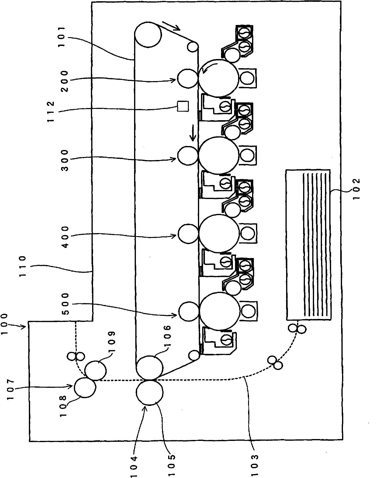
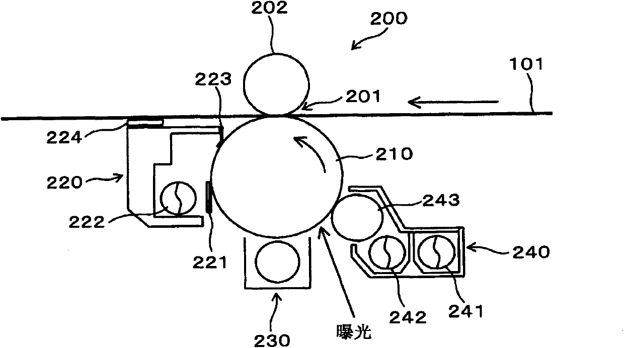
[0050] The respective cleaning blades thus produced were installed in the image forming apparatus. The edge of the cleaning blade was cut into the photoreceptor by 1.2 mm, and the angle formed by the cleaning blade and the tangent to the surface of the photoreceptor was set to 26°. Printing was performed on 7000 A4-size sheets conveyed in the longitudinal direction in an environment of a temperature of 28°C and a humidity of 85% and an environment of a...


PUM


Abstract

A cleaning blade includes a cleaning layer facing an image holding body, and a back layer wich is disposed at a side opposite to the image holding body and removes discharge products and developer residues that are stuck to a surface of the image holding body in such a manner that an edge of the cleaning layer comes into contact with the surface of the image holding body, and the back layer and the cleaning layer are molded integrally and a surface roughness Ra of the cleaning layer is lower than or equal to 0.12 mum.

Description

technical field [0001] The present invention relates to a cleaning blade used in an image forming apparatus and the image forming apparatus. Background technique [0002] In equipment based on electrophotography such as copiers, printers, facsimile machines, and multifunctional machines having these functions, after the toner image is transferred from the photoreceptor to the transfer target medium or member, the remaining residue is removed by the cleaning blade. Residual developer on the surface of the photoreceptor. In recent years, it is desired to extend the service life of the image forming unit and to make the cleaning blade highly durable. [0003] Traditional cleaning blades are single layer. And there is such a problem that if the cleaning blade is made harder to enhance durability, the degree of frictional wear of the photoreceptor increases or the cleaning blade sags (when one side of the cleaning blade is supported, the end portion of the cleaning blade droop...

Claims


Application Information

Patent Timeline
Patent Type & Authority Applications(China)
IPC IPC(8): G03G21/00G03G15/00
CPCG03G21/0011G03G21/0017
Inventor 青岛琢
Owner FUJIFILM BUSINESS INNOVATION CORP
Why Eureka
Try Eureka