Optical power alarming method and equipment

A technology of optical power and equipment, applied in the network field, can solve problems such as the uncertainty of judgment results

Inactive Publication Date: 2011-09-28
HUAWEI TECH CO LTD
View PDF2 Cites 7 Cited by
  • Summary
  • Abstract
  • Description
  • Claims
  • Application Information

AI Technical Summary

Problems solved by technology

[0004] Embodiments of the present invention provide an optical power alarm method and device to solve the problem of the need to rely on the experience of engineers to determine whether the optical power of the

Method used


Image

  • Optical power alarming method and equipment
  • Optical power alarming method and equipment
  • Optical power alarming method and equipment

Examples


Embodiment Construction

[0024] In order to solve the problem in the prior art that it is necessary to rely on the experience of the engineering personnel to determine whether the optical power of the optical signal received by the transmitting and receiving device exceeds the range of the optical power that the receiving device can withstand, the judgment result has a certain degree of uncertainty. The embodiment of the present invention provides a method and device for an optical power alarm.

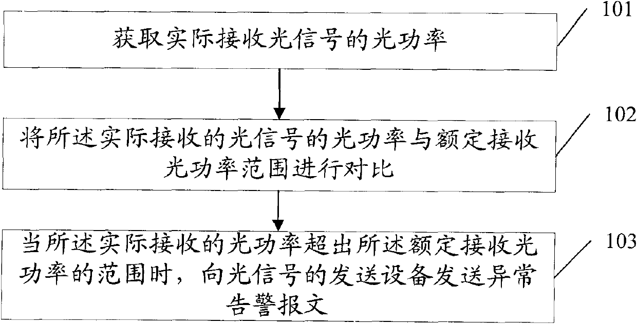
[0025] Such as figure 1 As shown, the optical power alarm method provided by the embodiment of the present invention includes:

[0026] Step 101: Obtain the optical power of the actually received optical signal.

[0027] In step 101, the network device may read the optical power of the optical signal actually received by the network device from the optical module register with the optical power detection function, so as to obtain the optical power of the actually received optical signal.

[0028] Optionally, the netw...


PUM


Abstract

The embodiment of the invention discloses an optical power alarming method and equipment, which relate to the technical field of networks and aim to solve the problem that a judgment result is uncertain to a certain extent because the optical power of an optical signal received by receiving equipment is required to be judged whether to exceed the range of optical power tolerable for the receiving equipment or not by the experiences of engineers in an equipment mounting process. The technical scheme provided by the invention comprises the following steps of: acquiring the optical power of an actually received optical signal; comparing the optical power of the actually received optical signal with a rated received optical power range; and if the optical power of the actually received optical signal exceeds the rated received optical power range, transmitting an abnormity alarming message to the transmission equipment of the optical signal. The optical power alarming method, the equipment and an optical power alarming system provided by the embodiment of the invention can be applied to packet communication networks.

Description

Technical field [0001] The present invention relates to the field of network technology, in particular to a method and equipment for optical power alarm. Background technique [0002] Optical fiber network devices are interconnected by lasers. When the optical fiber network device is used as the optical signal transmission device, when the optical power of the optical signal sent by the laser of the optical fiber network device is too low, it will cause the optical signal receiving device and the transmitting device to be different. The unstable signal transmitted between the receiving device and the transmitting device may even cause the communication between the receiving device and the transmitting device; when the optical power of the optical signal sent by the laser of the optical fiber network device is too high, it will cause the receiving device of the optical signal to be unable to withstand Damage occurs due to excessive optical signal. In the actual network installati...

Claims


Application Information

Patent Timeline
IPC IPC(8): H04L12/26H04B10/08H04B10/17H04B10/07
Inventor 陈建群
Owner HUAWEI TECH CO LTD
Why Eureka
Try Eureka