Linear guide rail locking device with protecting function

A linear guide, locking device technology, applied in metal processing equipment, metal processing mechanical parts, manufacturing tools, etc., can solve the problems of guide rail damage, small cylinder clamping force, inability to apply to medium and large machine tools, etc., to increase locking force effect

Inactive Publication Date: 2013-04-03
SANY GRP
View PDF5 Cites 2 Cited by
  • Summary
  • Abstract
  • Description
  • Claims
  • Application Information

AI Technical Summary

Problems solved by technology

However, it has the following technical problems: the clamping force of the oil cylinder is small, and excessive clamping force will cause damage to the guide rail, so it cannot be applied to medium and large machine tools

Method used


Image

  • Linear guide rail locking device with protecting function

Examples


Embodiment Construction

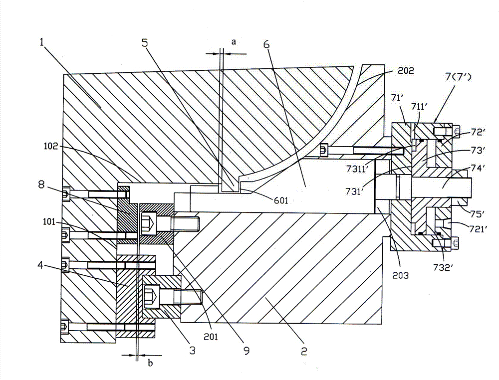
[0014] see figure 1 , a protective linear guide rail locking device of the present invention is arranged between the movable part 1 and the fixed part 2 of the machine tool, and the movable part 1 is slid on the linear guide rail 3 of the fixed part 2; wherein, the movable One side of the component 1 relative to the fixed component 2 is L-shaped, one side 101 is provided with a guide rail slider 4 that is fitted with the linear guide rail 3 of the fixed component 2, and the other side 102 is protruded along the length direction with a strip-shaped limit block or several limit blocks Block 5; the fixed part 2 is arranged on the side of the movable part 1 where the guide rail slider 4 is installed, and a side 201 corresponding to the guide rail slider 4 is provided with a linear guide rail 3 for the cooperation of the guide rail slider 4; the fixed part 2 is correspondingly movable A side 202 of the upper limit block 5 of the part 1 is provided with a plurality of through holes ...


PUM


Abstract

The invention discloses a linear guide rail locking device with a protecting function. The linear guide rail locking device is arranged between a moving part and a fixed part of a machine tool. The lateral surface of the moving part, which is opposite to the fixed part, is L-shaped; a guide rail sliding block is arranged on one surface of the moving part; a strip-shaped limiting block or a plurality of limiting blocks are convexly arranged on the other surface of the moving part along the length direction; a linear guide rail is arranged on the lateral surface of the fixed part, which corresponds to the guide rail sliding block; a plurality of through holes are parallelly formed in the lateral surface of the fixed part, which corresponds to the liming block, along the length direction; push rods are respectively arranged in the through holes; a groove is formed at the end of each push rod, which corresponds to the limiting block; a plurality of driving mechanisms are arranged on the outer lateral surfaces of the through holes of the fixed part and are connected with the push rods; and a first protecting block and a second protecting block are relatively arranged on the moving partand the fixed part. According to the linear guide rail locking device disclosed by the invention, a locking oil cylinder is arranged at a position outside the guide rails to avoid the space limit of the traditional arrangement, so that the size and the number of the oil cylinders can be better selected personally and further a larger locking force can be provided; and by arranging the protecting device, the linear guide rail can be better protected by using the large locking force.

Description

technical field [0001] The invention relates to machine tool equipment, in particular to a linear guide rail locking device with protection. Background technique [0002] In machine tool processing, the fixed processing of machine tools is favored for its high precision, good rigidity, and adaptability to high power and high torque. This is especially true for turn-mill compound machine tools. The turn-mill compound machine tool adds a Y-axis to the lathe, making it capable of powerful milling. However, the added Y-axis will not be used in the turning process, but will affect the processing of the entire machine tool. Therefore, it is very important to lock the Y axis during the turning process. [0003] The most common way to lock the guide rail is to install the special hydraulic locking mechanism directly on the linear guide to realize the action of mechanical locking and hydraulic release. There are more professional manufacturers to do this locking mechanism at home a...

Claims


Application Information

Patent Timeline
Patent Type & Authority Patents(China)
IPC IPC(8): B23Q1/26
Inventor 赖修颖鲁理政祝闰红
Owner SANY GRP
Why Eureka
Try Eureka