Reposition device for spinal column and occipital bone, and connecting device of reposition stick with bone screws

A reset device and technology of the occipital bone, which is applied in the medical field, can solve the problems of difficulty in accommodating and locking the locking rod parts, small space for the occipital bone, and protruding outwards of the surgical position of the occipital bone, and achieves the effect of convenient operation of the locking rod and simple structure

Active Publication Date: 2014-06-25
SHANGHAI SANYOU MEDICAL CO LTD
View PDF3 Cites 0 Cited by
  • Summary
  • Abstract
  • Description
  • Claims
  • Application Information

AI Technical Summary

Problems solved by technology

[0005] According to the above content, the lock rod part is mainly the lock nut 13, and the locking of the reset rod 12 depends on the lock nut 13 directly against the reset rod 12, and it is locked in the through groove, so the radial orientation of the reset rod 12 Need to reserve a certain space to accommodate the locking rod parts, such as Figure 1 to Figure 3 There is an internal thread section for the locking nut 13 to be screwed in above the through groove for accommodating the reset rod 12. When the operating space above the reset rod 12 is insufficient or limited, it is difficult to accommodate and lock the locking rod parts. For example, when the internal fixation operation is performed on the occipital bone, the locking method in the prior art is adopted, the overall thickness of the reset rod 12 and the lock nut 13 after being superimposed is relatively large, and the space of the occipital bone along the thickness direction of the reset rod 12 is small. The surgical site of the occipital bone tends to bulge outward after the surgery

Method used


Image

  • Reposition device for spinal column and occipital bone, and connecting device of reposition stick with bone screws
  • Reposition device for spinal column and occipital bone, and connecting device of reposition stick with bone screws
  • Reposition device for spinal column and occipital bone, and connecting device of reposition stick with bone screws

Examples


Embodiment Construction

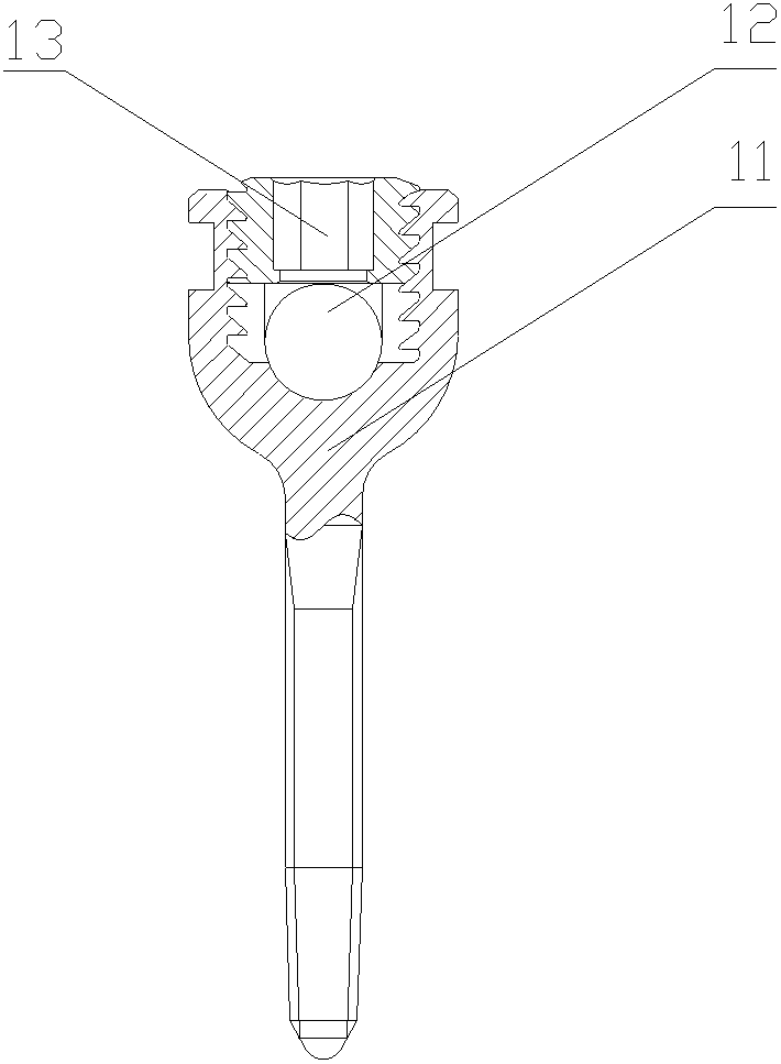
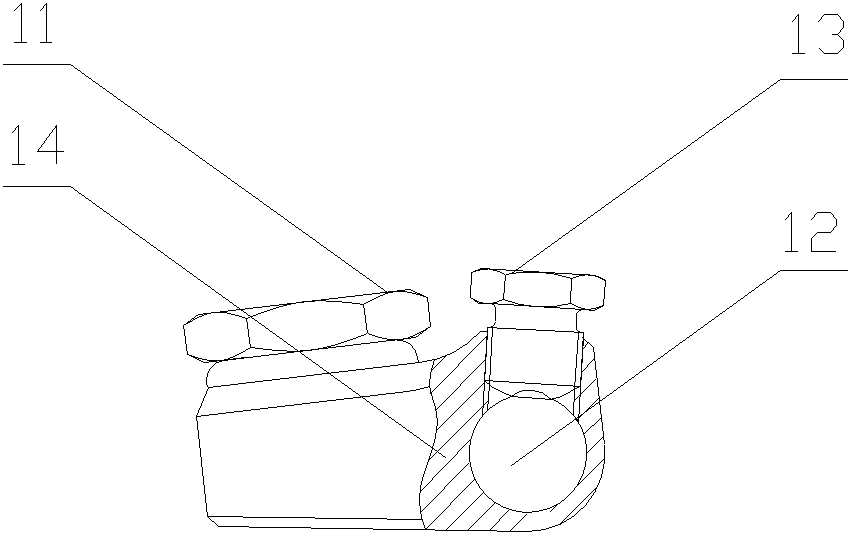
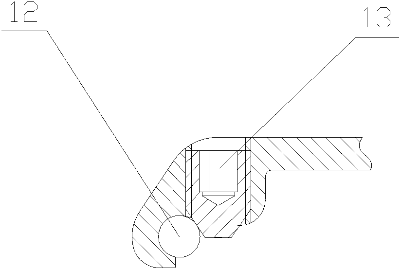
[0034] The core of the present invention is to provide a connecting device for a reset rod and a bone screw, the connecting device can separate the locking rod part from the reset rod, so that the connecting device can be used in the case of insufficient space. Another core of the present invention is to provide a reset device for the spine and occiput including the above connecting device.

[0035] In order to enable those skilled in the art to better understand the technical solutions of the present invention, the present invention will be further described in detail below in conjunction with the accompanying drawings and specific embodiments. In order to facilitate the understanding of the technical solution of the present invention, the following embodiments combine the connection device provided by the present invention with the provided reset device for description, and the embodiment of the reset device will not be described repeatedly, and its beneficial effects are com...


PUM


Abstract

The invention discloses a reposition device for spine and occipital bone, which comprises bone screws and connecting device. The connecting device comprises a tube body through which the reposition stick runs, wherein an opening is formed on the tube body along the length direction thereof; externally extended fastening sides are arranged on both opening sides; the surfaces of the two fastening sides are opposite to each other, and the connecting device comprises at least one pair of connection holes which are formed on the two fastening sides coaxially; and the pair of connection holes have at least one through hole, and the bone screw run through a pair of coaxial connecting holes. The connecting device can be used for positioning the reposition stick in the tube body; the fastening sides can be closed by using a stick locking member to drive tightening of the tube body, so that the reposition stick is locked tightly, and the stick locking member and the reposition stick can be arranged separately, as a result, a space for holding the stick locking member is not needed to be pre-formed on the reposition stick during an operation, and a fixing operation can be implemented in a limited space conveniently; furthermore, the connecting device is simple in structure and capable of realizing stick locking operation of the stick locking member conveniently.

Description

technical field [0001] The invention relates to the field of medical technology, in particular to a reset device for spine and occiput. Background technique [0002] With the development of biomechanical research and material science, the application of internal fixation technology has become more and more extensive, and it has been widely used in the surgical treatment of spinal degenerative diseases, spinal tumors, trauma and even spinal infection. The reset device includes a bone screw, a lock nut and a reset rod. Usually, a lock nut is placed above the reset rod, and the lock nut can be tightened to achieve a locked connection between the reset rod and the bone screw. [0003] Please refer to Figure 1 to Figure 3 , figure 1 It is a schematic diagram of the first connection mode between the bone screw and the reduction rod in the prior art; figure 2 It is a schematic diagram of the second connection mode between the bone screw and the reduction rod in the prior art; ...

Claims


Application Information

Patent Timeline
Patent Type & Authority Patents(China)
IPC IPC(8): A61B17/84A61B17/70
Inventor 倪斌邬春晖
Owner SHANGHAI SANYOU MEDICAL CO LTD
Why Eureka
Try Eureka