Corner roller for ribbon conveyer bending device

A technology of belt conveyor and turning device, applied in the direction of conveyor, transportation and packaging, can solve the problems of friction damage of conveyor belt and large local stress of conveyor belt.

Inactive Publication Date: 2013-03-27
HENAN POLYTECHNIC UNIV
View PDF1 Cites 0 Cited by
  • Summary
  • Abstract
  • Description
  • Claims
  • Application Information

AI Technical Summary

Problems solved by technology

However, practice has proved that the method of arranging small idlers cannot completely solve the problem of large local stress on the conveyor belt because there is always a space between the end faces of adjacent small idlers and there is an angle between the axes.
The small idlers with non-linear busbars will also cause friction damage to the conveyor belt due to the unequal linear speed of each point in contact with the conveyor belt

Method used


Image

  • Corner roller for ribbon conveyer bending device
  • Corner roller for ribbon conveyer bending device
  • Corner roller for ribbon conveyer bending device

Examples


Embodiment Construction

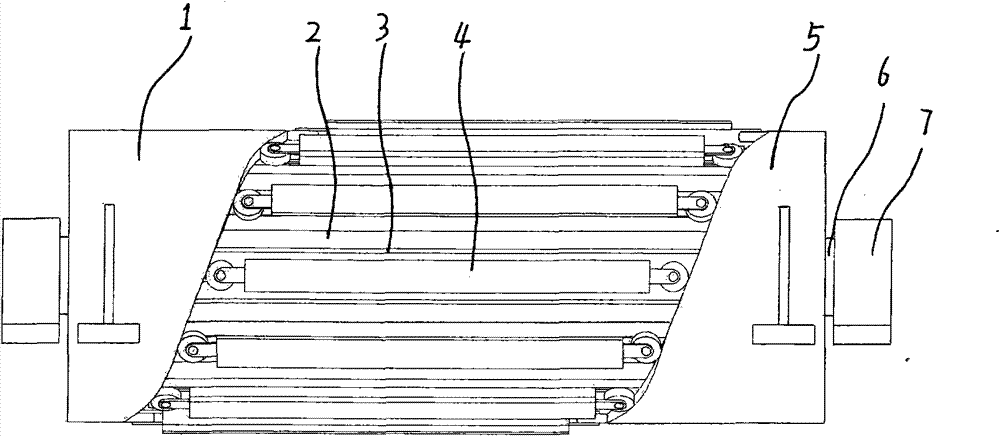
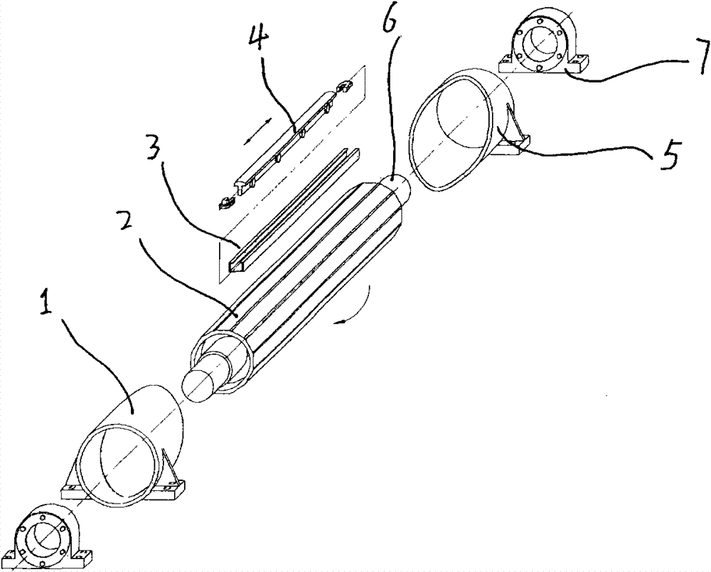
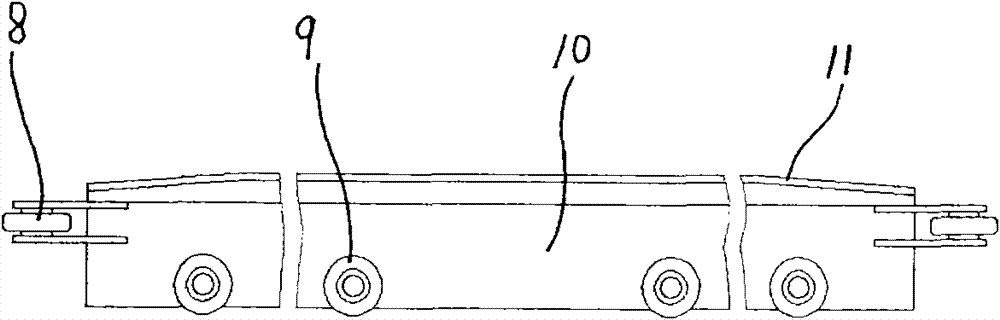
[0012] Depend on figure 1 , figure 2 , image 3 It can be seen that the present invention includes: left cylindrical cam 1, rotating drum 2, guide rail 3, conveyor belt support 4, right cylindrical cam 5, rotating shaft 6, shaft seat 7, rotating shaft 6 penetrates and is arranged in the shaft seat 7 at both ends, The rotating shaft can rotate in the shaft seat. A rotating drum 2 is fixedly arranged on the rotating shaft 6, and the rotating shaft rotates coaxially with the rotating drum. A number of guide rails 3 are evenly spaced in the axial direction around the surface of the rotating drum 2, and a conveyor belt support 4 is provided in the guide rail 3, and each guide rail 3 is fitted with a guide rail that can be parallel to the axis of the roller along the guide rail. Moving conveyor belt supports. The conveyor belt support is composed of guide rollers 8, support rollers 9, support body 10, and rubber layer 11. In order to ensure that the conveyor belt support 4 can ...


PUM


Abstract

The invention discloses a corner roller for a ribbon conveyer bending device. The corner roller comprises a left cylindrical cam, a rotation roller, guide rails, conveying belt bearing parts, a right cylindrical cam, a revolving shaft, and shaft seats; the revolving shaft passes through and is arranged in the shaft seats at two ends; the revolving shaft is fixedly provided with the rotation roller; a plurality of guide rails are uniformly arranged round the surface of the rotation roller in the axial direction; the conveying belt bearing parts which are matched with the guide rails are arranged in the guide rails; the left end of the rotation roller is fixedly provided with the left cylindrical cam; the right end of the rotation roller is fixedly provided with the right cylindrical cam; two tips of the conveying belt bearing parts are slidably contacted with the annular surface of the left cylindrical cam and the annular surface of the right cylindrical cam; support rollers are respectively arranged at the two sides of the lower portion of the conveying belt bearing parts, the two ends of the support are respectively provided with guide rollers, wherein the support rollers are located in the guide rail. A conveying rubber belt runs on the corner roller; and the corner roller has the characteristics of uniform stress, small frictional wear, high multi-turning-angle adaptability and the like.

Description

Technical field: [0001] The invention belongs to the technical field of belt conveyor turning devices. Background technique: [0002] At present, the working principle and structure of the corner rollers in the turning device of the belt conveyor are basically the same, and a number of small rollers are regularly arranged on the circumferential surface of the conveyor belt, so that each small roller The axial direction of the conveyor belt is perpendicular to the running direction of the conveyor belt, and the conveyor belt runs on the outer peripheral envelope surface of all the small rollers, such as the patent No. 92232596.0, which is called the patent publication of the corner reversing roller of the belt conveyor. Although such a corner roller device solves the basic problem of the turning operation of the conveyor belt, since there is an angle between the axis of each small idler roller and the axis of the corner roller, the place where the two ends of the small idler ...

Claims


Application Information

Patent Timeline
Patent Type & Authority Patents(China)
IPC IPC(8): B65G15/62
Inventor 刘志忠姬玉荣孟凡波孟凡茂张丽梅
Owner HENAN POLYTECHNIC UNIV
Why Eureka
Try Eureka