Supercharge Your Innovation With Domain-Expert AI Agents!

Coupling device for support member

A technology for coupling devices and components, which is applied in the field preparation and construction of pillars and building components, can solve the problems of unfavorable construction period and cost, the absence of latch rods kept in the pulled-out state, and the cost of work, etc., to achieve reduction Time and cost, prevention of accidental lifting and falling off, effect of smooth connection work

Inactive Publication Date: 2011-10-12
拉里克有限公司
View PDF7 Cites 5 Cited by
  • Summary
  • Abstract
  • Description
  • Claims
  • Application Information

AI Technical Summary

Problems solved by technology

Therefore, in order to pull out the latch rod for disassembly etc. from this coupled state, the latch rod must be reversely rotated 90 degrees again. In view of the large number of connection parts of the bracket, it is very laborious to perform this reverse rotation operation on all the latch rods during the disassembly operation. quantity, which is unfavorable in terms of both duration and cost
[0012] In addition, the component coupling devices of Patent Documents 1 and 2 do not have a mechanism for maintaining the latch bar in a pulled-out state.

Method used


Image

  • Coupling device for support member
  • Coupling device for support member
  • Coupling device for support member

Examples


Embodiment Construction

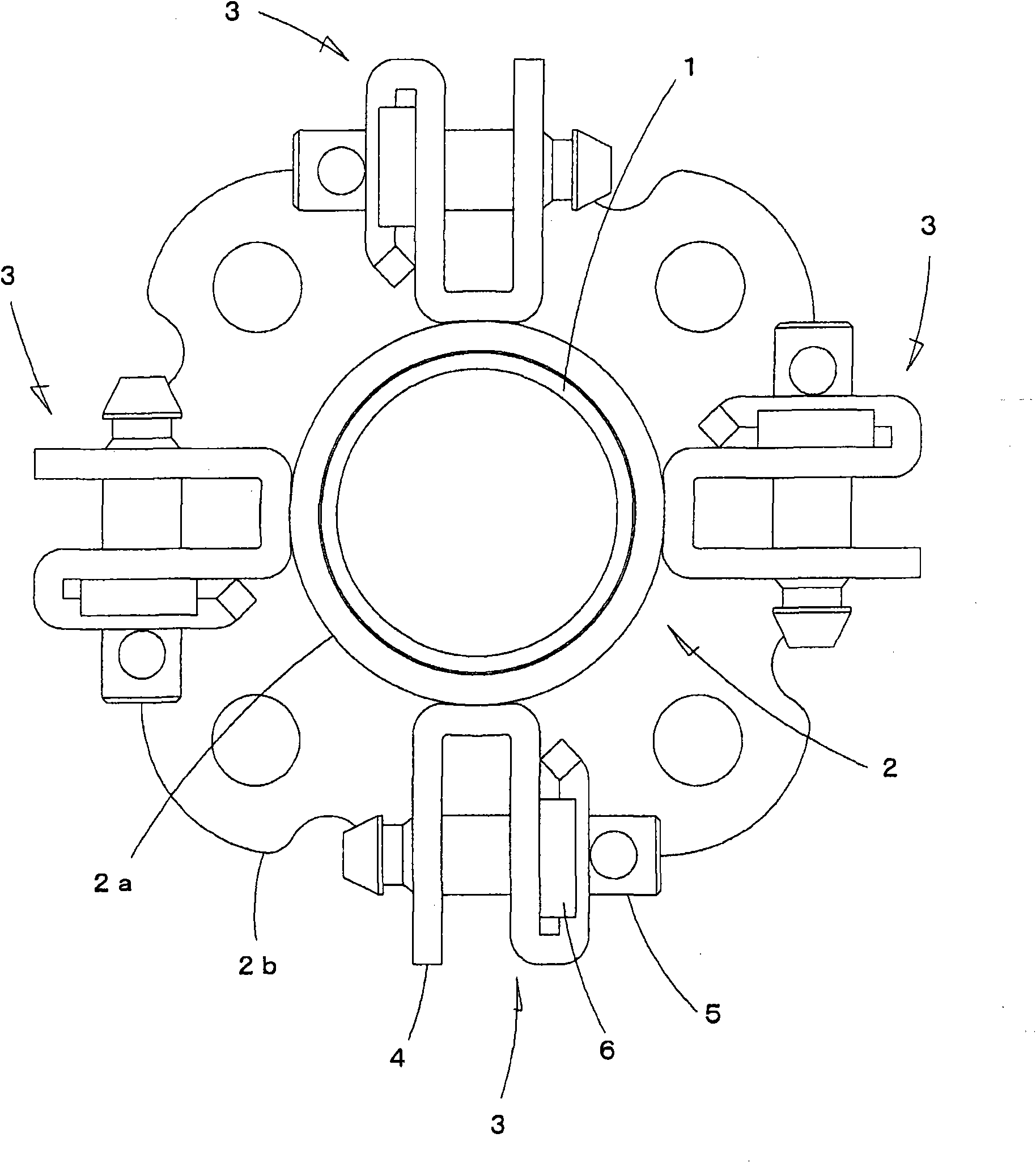
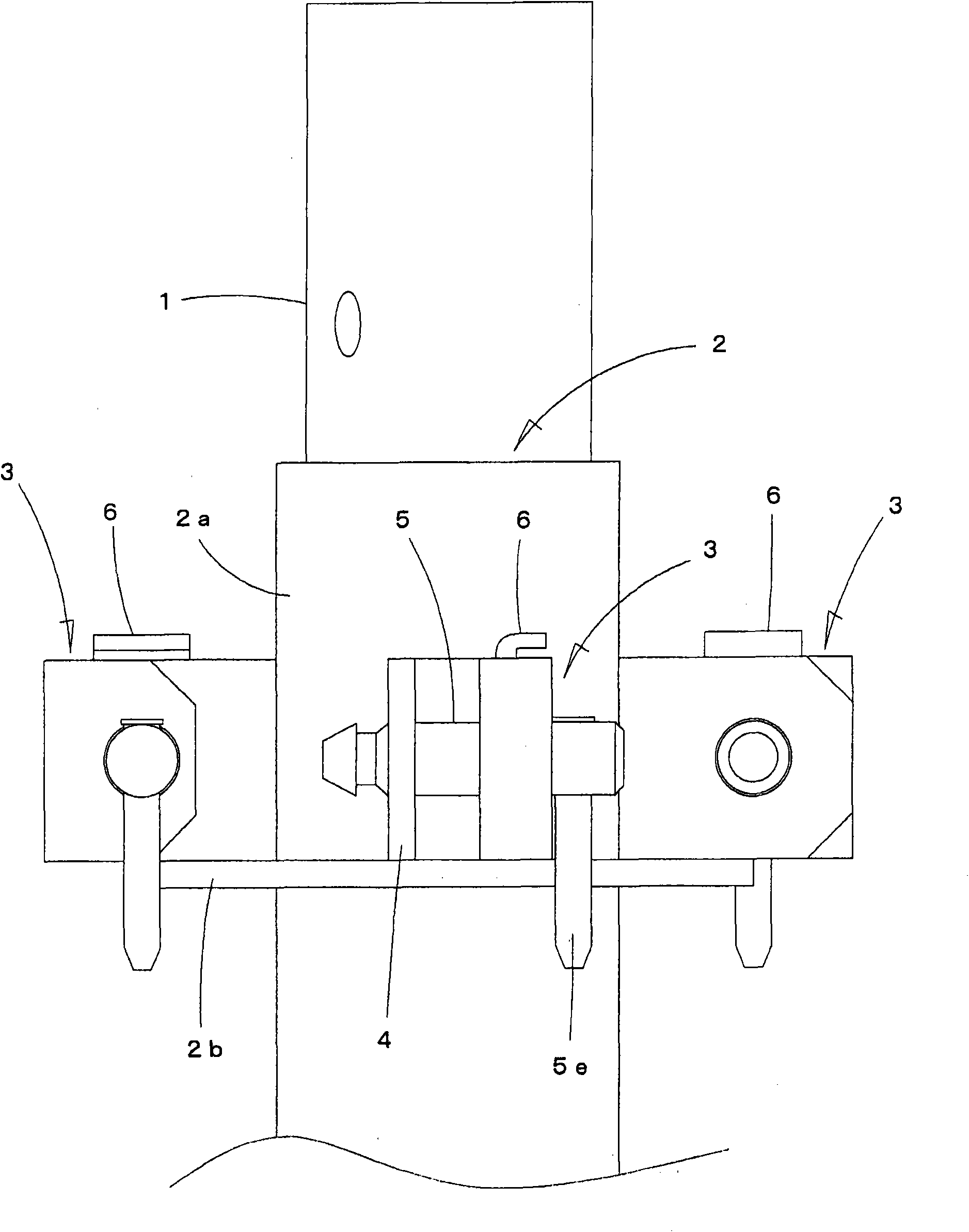
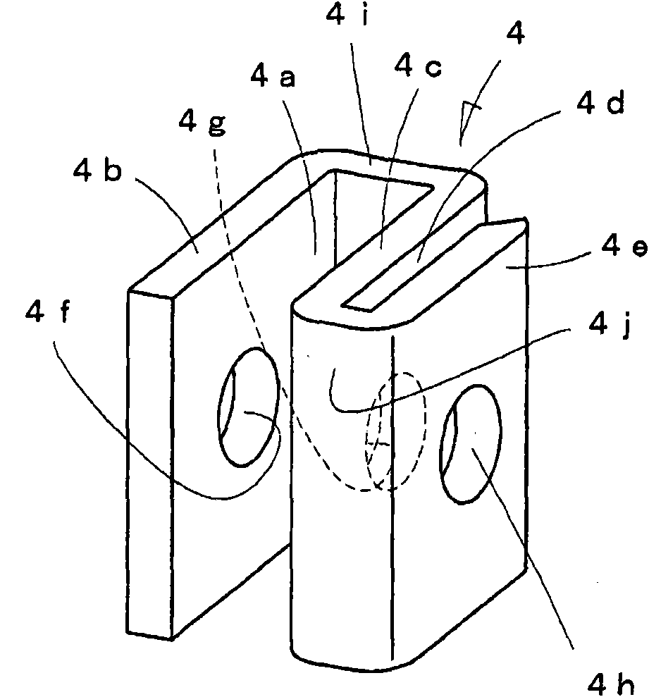
[0038] Hereinafter, preferred embodiments of the present invention will be described in accordance with the drawings. figure 1 , figure 2 A plan view and a side view showing a component coupling device of a stent according to an embodiment of the present invention. In this figure, 1 is a temporary support column, and 2 is a coupling mounted on a predetermined position of the support column 1 by fitting. The coupling 2 has a structure in which a vase-shaped flange 2b is provided on the lower surface of the support tube 2a. 3 is a component coupling device installed at four locations around the coupling 2 at equal angles by welding or the like. The component coupling device 3 is composed of a metal bracket 4, a latch bar 5 and a locking member 6. In addition, in this embodiment, four component coupling devices 3 are provided on one coupling 2, but the number may be 1 to 3, or 5 or more.

[0039] The metal bracket 4 as a structural component of the component coupling device 3 is a...


PUM


Abstract

The invention provides a coupling device for support members, wherein the coupling and disintegrated state can be conveniently realized only by sliding a latch rod. Meanwhile, the accidental sliding of the latch rod is avoided not only under the coupling state but also under the disintegrated state. The device comprises a metal support for bending one lateral part of two parallel connection plates, which also comprises a guiding plate part. The three plate parts are respectively equipped with insertion holes communicated with each other. A latch rod is inserted inside the insertion hole of the metal support by sliding from the guiding plate part to another connection plate part. A locking member can be moved toward the latch rod from the upper part thereof between the guiding plate part and one parallel connection plate part. The front and rear two positions at the circumferential surface of the latch rod are formed with locking recesses. A locking tool can be locked only under the coupling state that the latch rod is inserted into the insertion holes of the three plate parts and under the releasing state that the latch rod is inserted into the insertion holes of the guiding plate part and one of the parallel plate parts.

Description

Technical field [0001] The present invention relates to a component coupling device that connects a temporarily installed component for reinforcement such as a diagonal brace to a temporarily installed pillar by inserting and removing a latch rod, and relates to a component coupling and disassembling operation that makes the latch rod easier than before Improved structure. Background technique [0002] Scaffolds and support templates at construction sites are constructed by connecting diagonal braces or horizontal tie rods to temporarily installed pillars. In this connection, as disclosed in Patent Documents 1 and 2, a component connecting device using a latch bar is used. [0003] In the component coupling device of Patent Document 1, four metal brackets are welded at 90° intervals on the outer circumference of a cylindrical body mounted on a pillar, and the ends of diagonal braces or horizontal tie rods are connected to the metal brackets. A device in which the metal bracket is ...

Claims


Application Information

Patent Timeline
IPC IPC(8): E04G25/06
Inventor 藤城忠彦
Owner 拉里克有限公司
Features
  • R&D
  • Intellectual Property
  • Life Sciences
  • Materials
  • Tech Scout
  • Unparalleled Data Quality
  • Higher Quality Content
  • 60% Fewer Hallucinations
Learn More