Method of forming a tubular blank into a structural component and die therefor

a tubular blank and structural component technology, applied in the direction of shaping tools, heat treatment equipment, furnaces, etc., can solve the problem that the control of the heating profile cannot be done in the prior hydroforming process, and achieve the effect of improving the material formability of the metal blank, low die life, and high equipment costs

Inactive Publication Date: 2006-04-11
HOT METAL GAS FORMING IP2 INC +1
View PDF27 Cites 47 Cited by
  • Summary
  • Abstract
  • Description
  • Claims
  • Application Information

AI Technical Summary

Benefits of technology

[0017]The forming process of the present invention reduces the cost to process formed structural components by 30–50% or more and reduces the time to build, and the cost to build the forming die members by at least about 20–40% or more. By using structural components formed by the unique process of the present invention, the structural component is reduced in weight by about 5–20% or more. Although the inventive method typically involves the use of a fluid in the form of gas to expand the sheet metal shaped blank into the desired configuration for the structural element, the invention actually involves substantial improvements in this general process. In other words, the present invention is not merely the use of high pressure gas as a substitute for high pressure liquid used in hydroforming. As a result, one or more of the improvements of the present invention can be used in prior hydroforming processes to improve the efficiencies of metal forming, to reduce the time and / or cost of metal forming, and / or to form superior structural components.
[0084]Yet a further and / or alternative object of the present invention is the provision of an apparatus and / or method, as defined above, which apparatus and / or method includes the use of one or more induction heating coils within the die which induction heating coils have a uniform or varied space location from the surface of the die surface, so as to provide desired heating profiles to the metal blank and / or to reduce thermal shock to the die during the forming process.

Problems solved by technology

Such a controlled heating profile cannot be done in prior hydroforming processes.

Method used


Image

  • Method of forming a tubular blank into a structural component and die therefor
  • Method of forming a tubular blank into a structural component and die therefor
  • Method of forming a tubular blank into a structural component and die therefor

Examples


Embodiment Construction

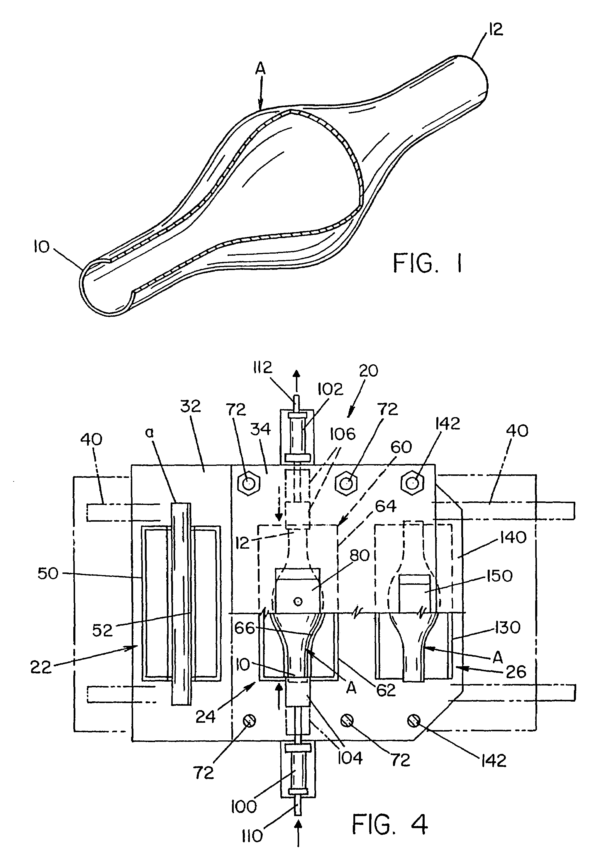
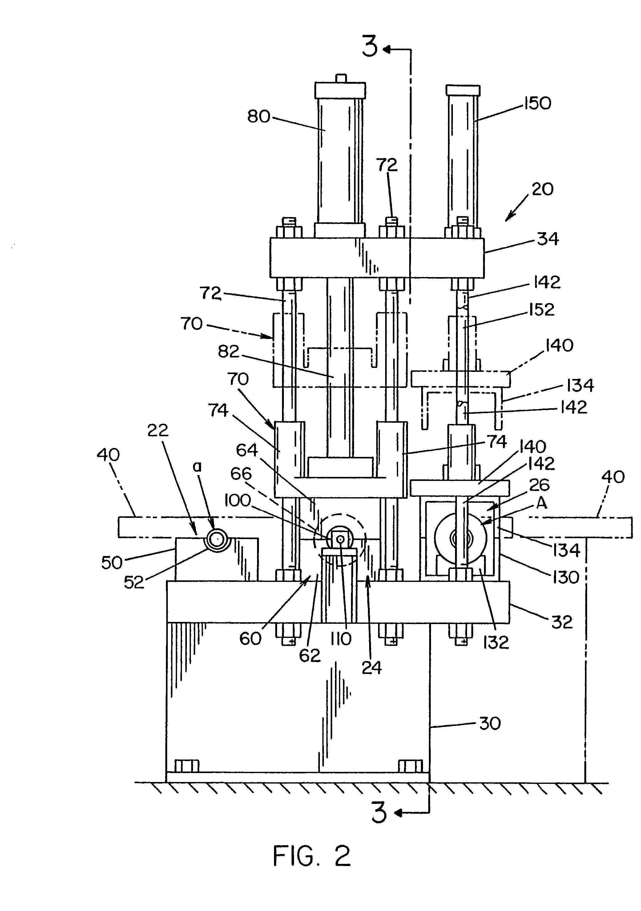
[0138]Referring now to the drawings wherein the showings are for the purpose of illustrating the preferred embodiments only and not for the purpose of limiting same, FIG. 1 illustrates a finished tubular structural component A formed by using the preferred embodiment of the present invention as schematically illustrated as machine 20 in FIGS. 2–6. Structural component A is illustrated as a quite simple shape for ease of discussion. Other more complex shapes of the structural component are illustrated in FIGS. 7–9, 39A, 39B, and 40–43B. As can be appreciated, many other shapes of the structural component can be formed in accordance with the present invention. For purposes of illustrating the present invention, the disclosure associated with the simple shape of component A applies to all shapes. Structural component A is typically made of a metal material such as, but not limited to, carbon steel, stainless steel, aluminum, magnesium and the like. As will be described in more detail b...


PUM

PropertyMeasurementUnit
pressureaaaaaaaaaa
temperaturesaaaaaaaaaa

Abstract

A method of forming an elongated metal blank into a structural component having a predetermined outer configuration. The method includes providing a shape imparting cavity or shell section formed from a rigid material which includes an inner surface defining the predetermined shape, placing the metal blank into the cavity or shell section, and forming the metal blank into the component by heating axial portions of the metal blank and forcing a fluid at a high pressure into the metal blank until the metal blank at least partially conforms to at least a portion of the inner surface of the cavity or shell section to form the structural component.

Description

[0001]The present invention is a continuation-in-part of U.S. patent application Ser. No. 10 / 613,642 filed Jul. 3, 2003 entitled “Method of Forming a Tubular Blank into a Structural Component and Die Therefor,” which in turn is a continuation of U.S. patent application Ser. No. 09 / 944,769 filed Sep. 4, 2001 entitled “Method of Forming a Tubular Blank into a Structural Component and Die Therefor,” now U.S. Pat. No. 6,613,164, which in turn is a continuation of U.S. patent application Ser. No. 09 / 481,376 filed Jan. 11, 2000 entitled “Method of Forming a Tubular Blank into a Structural Component and Die Therefor,” now U.S. Pat. No. 6,322,645, which in turn claims priority of U.S. Provisional Patent Application Ser. No. 60 / 155,969 filed Sep. 24, 1999 entitled “Method of Forming a Tubular Blank into a Structural Component and Die Therefor.”[0002]The present invention also claims priority on co-pending U.S. Provisional Patent Application Ser. No. 60 / 409,788 filed Sep. 11, 2002 entitled “I...

Claims


Application Information

Patent Timeline
Patent Type & Authority Patents(United States)
IPC IPC(8): B21D26/02C22F1/00
CPCB21D26/033B21D26/043B21D37/16B21D26/047Y10T29/49805Y10S72/709
Inventor PFAFFMANN, GEORGE D.DYKSTRA, WILLIAM C.MATSEN, MARC R.
Owner HOT METAL GAS FORMING IP2 INC
Why Eureka
Try Eureka