Modular system of permanent forms for casting reinforced concrete buildings on site

a permanent form and concrete technology, applied in the field of modular building assembly, monolithic post and beam reinforced concrete structure, can solve the problems of increasing the cost of factory labor, and increasing the cost of steel frame construction, so as to reduce the overall weight of the building, the effect of reducing the volume of concrete used and reducing the size of the shoring and the footing

Inactive Publication Date: 2007-03-06
MARTY OSCAR
View PDF47 Cites 49 Cited by
  • Summary
  • Abstract
  • Description
  • Claims
  • Application Information

AI Technical Summary

Benefits of technology

[0017]It is an object of the present invention to provide a modular system of permanent forms for constructing reinforced concrete buildings where the volume of concrete used and the overall weight of the building are reduced. It is another object of the present invention to provide for a reduction in steel reinforcement materials and in the labor required to assemble the steel reinforcement. It is a further object of the present invention to provide for a reduction in shoring and in footing sizes. It is still another object of the present invention to provide for a reduction of time required in forming (making concrete forms), form removal and overall construction. It is yet another object of the present invention to reduce transportation costs by reducing the weight of the precast concrete components. It is another object is to provide for a reduction in capital costs, which are tied up in temporary forms, their installation, removal, care and storage. Finally, it is an object of the present invention to increase the quality of the building.
[0018]The present invention achieves these and other objectives (1) by providing a relatively lightweight, prefabricated building component that is erected on site and reinforced with poured concrete and (2) by providing a prefabricated construction system for reinforced concrete buildings. The system employs a variety of precast glass-fiber reinforced concrete (GRC) components such as walls, flooring, roofs, columns, beams, etc. The system is amenable for use in a variety of construction projects, including but not limited to retaining walls, above grade walls, and reinforced concrete buildings. The system is assembled over footings and / or a foundation. For reinforced concrete buildings, a foundation is made up of a concrete floor slab with the periphery depressed or stepped to receive precast GRC wall panels. The depressed or stepped periphery minimizes mechanically the infiltration of water into the structure.
[0019]The GRC components are made of a concrete material that is made up of a slurry of cement and sand with AR fibers, which give this matrix a high flexural strength. The high flexural strength of the material allows it to be used for secondary structural loads with a typical thickness of about ⅜ inches and weighing typically 4 to 5 pounds per square foot. Because of the material's high density, forms made with the typical thickness disclosed previously are impervious. Further the material's high density also allows for a reduction in the thickness of the concrete required for the protection of steel rods of the primary structural components cast on site. The relative thinness of the GRC coupled with its strength allows for the formation of very strong and lightweight precast forms that reduce the amount of the temporary shoring compared to conventional precast concrete forming techniques. In addition, the forms are fireproof. With respect to GRC components used for retaining walls, above grade walls, support beams, support columns, and the like, the lightweight components are assembled on site and serve as the permanent forms for receiving poured concrete.
[0021]The first and second vertical perimeters typically have flanges that project out of the plane of the inside face of the wall panel such that, when assembled with other wall panels, form a space or void between adjacent wall panels that is in communication with the U-shaped top perimeter of the wall panel. The wall panels have in their exterior vertical perimeters a wall panel mating connection that mates adjacent wall panels together. The wall panel bottom perimeter optionally has a lip on the outside face to overlap the exterior face of the top perimeter of another wall panel or the foundation floor slab to minimize, mechanically, water penetration into the building. Column steel reinforcements are placed into the voids and a GRC enclosing panel is installed between flanges of adjacent wall components enclosing the voids, which are to receive the concrete to form the building support columns. The wall components / panels come in a variety of shapes and sizes, have numerous configurations involving the location of precast openings for doors, windows, air conditioning / heating components, etc., or may be devoid of precast openings.
[0024]The present invention, which uses pre-cast GRC components as permanent forms for casting reinforced concrete buildings, retaining walls, etc., on site, has several distinct advantages over the prior art. Use of the present invention system particularly for building construction provides (1) a reduction in the volume of concrete by about 20 to about 30%, (2) a reduction in the use of steel reinforcement materials by about 10% to about 15%, (3) a reduction in labor for installation of the steel reinforcement by about 30% to about 45%, (4) a reduction in shoring by about 20% to about 30%, (5) a reduction in the overall weight of the building by about 20%, (6) a reduction in footing sizes and steel reinforcement by about 10% to about 20% (depending on building height and weight), (7) a reduction in labor time of about 20% to about 40% for formwork and form removal, and (8) a reduction in the amount of working capital tied up in temporary forms, their installation, remove, care, and storage.

Problems solved by technology

Steel frame construction is relatively expensive due to the expense of the structural steel and the skilled labor involved.
This method still requires extensive amounts of on-site labor, which can be quite expensive when compared to factory labor.
A disadvantage of the prior art regarding precast concrete structural components is that the structural systems depend on field point connections (e.g., welded steel plates, anchor bolts, post-tensioned cables, etc.).
The design redundancy increases the use of materials and requires highly skilled labor, supervision and costly quality controls at the building site.
The increased weight and size of these components requires costly transportation and expensive hoisting equipment.
Another problem with these systems is sealing and waterproofing their joints, which is very costly and has to be replaced and maintained every 5 to 10 years increasing greatly the cost of the building.
A disadvantage of the prior art regarding conventional form making at the job site is that the construction methods are time consuming, require intensive skilled labor, exposure to weather conditions that affect scheduling and quality control of the forms, limited dimensional accuracy and wasteful in material consumption.
Also, once the forms are stripped, the unfinished reinforced concrete surfaces require plastering or the use of other finishes like brick, tiles, stone, etc., unless expensive liners are used.

Method used


Image

  • Modular system of permanent forms for casting reinforced concrete buildings on site
  • Modular system of permanent forms for casting reinforced concrete buildings on site
  • Modular system of permanent forms for casting reinforced concrete buildings on site

Examples


Embodiment Construction

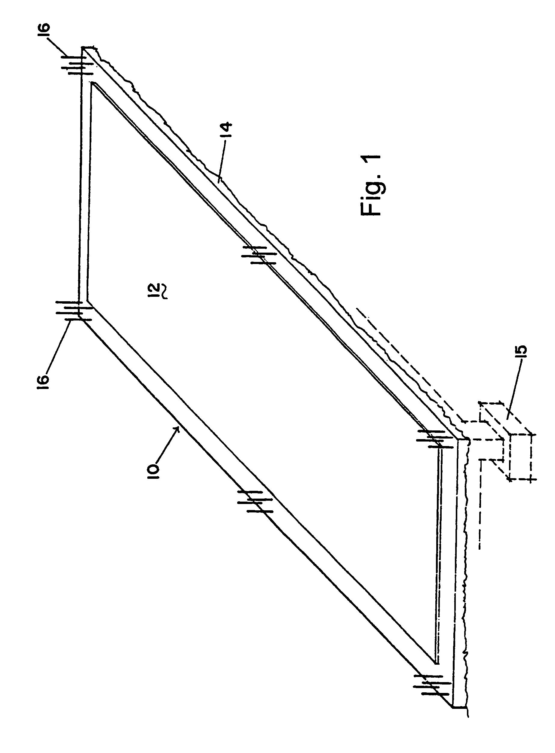
[0040]The preferred embodiment(s) of the present invention is illustrated in FIGS. 1–14. FIG. 1 illustrates a foundation 10 made up of a concrete floor slab 12 supported by a plurality of building footings below ground and represented by reference 15. The periphery 14 of concrete floor slab 12 is depressed or stepped to receive one or more pre-cast GRC wall panels (not shown). The depressed / stepped periphery 14 is designed to minimize mechanically the infiltration of water into the structure. Steel dowels 16 are installed at locations where building support columns will be formed. Steel dowels 16 are installed using a template to insure their precise location and arrangement.

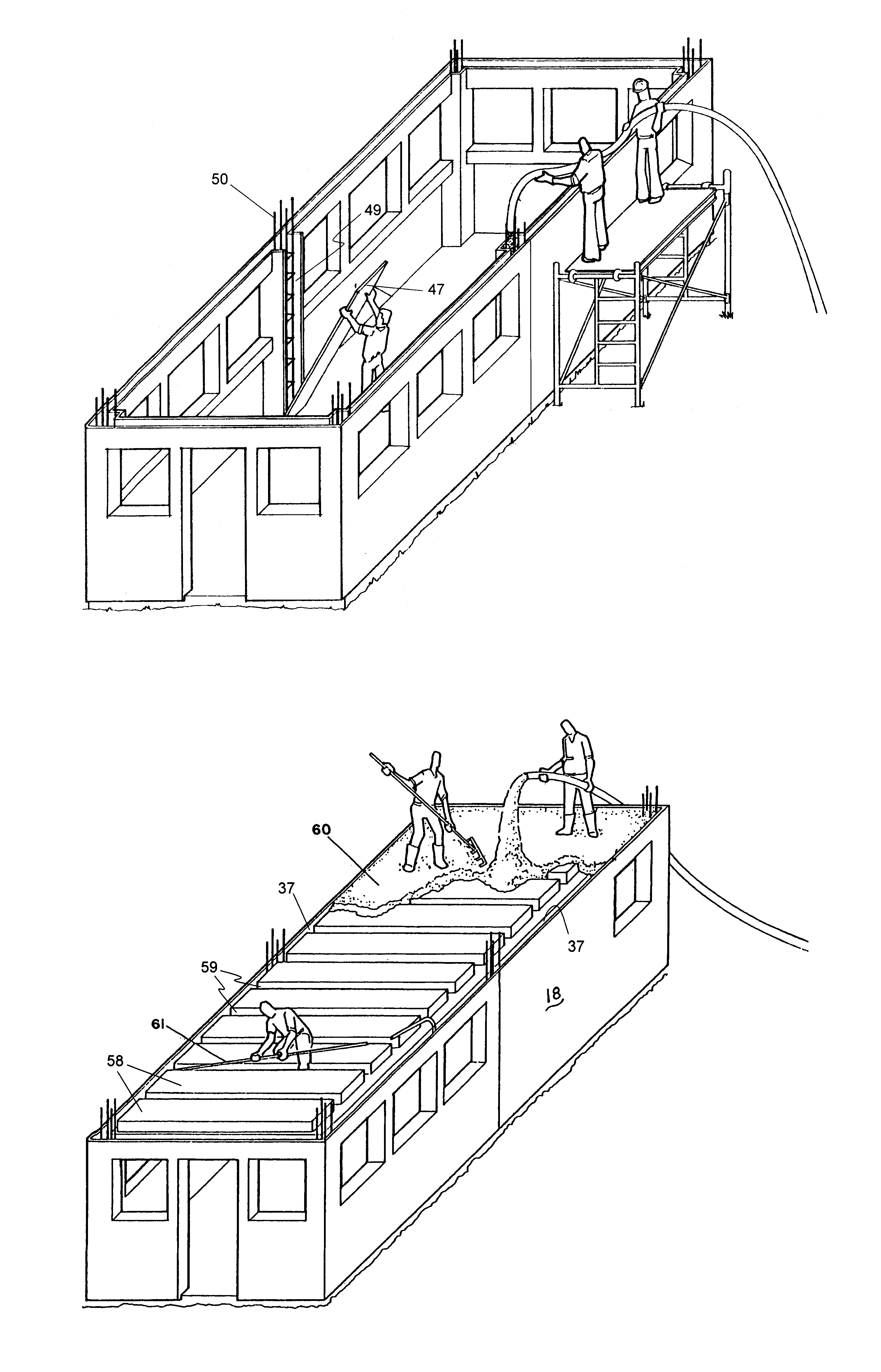
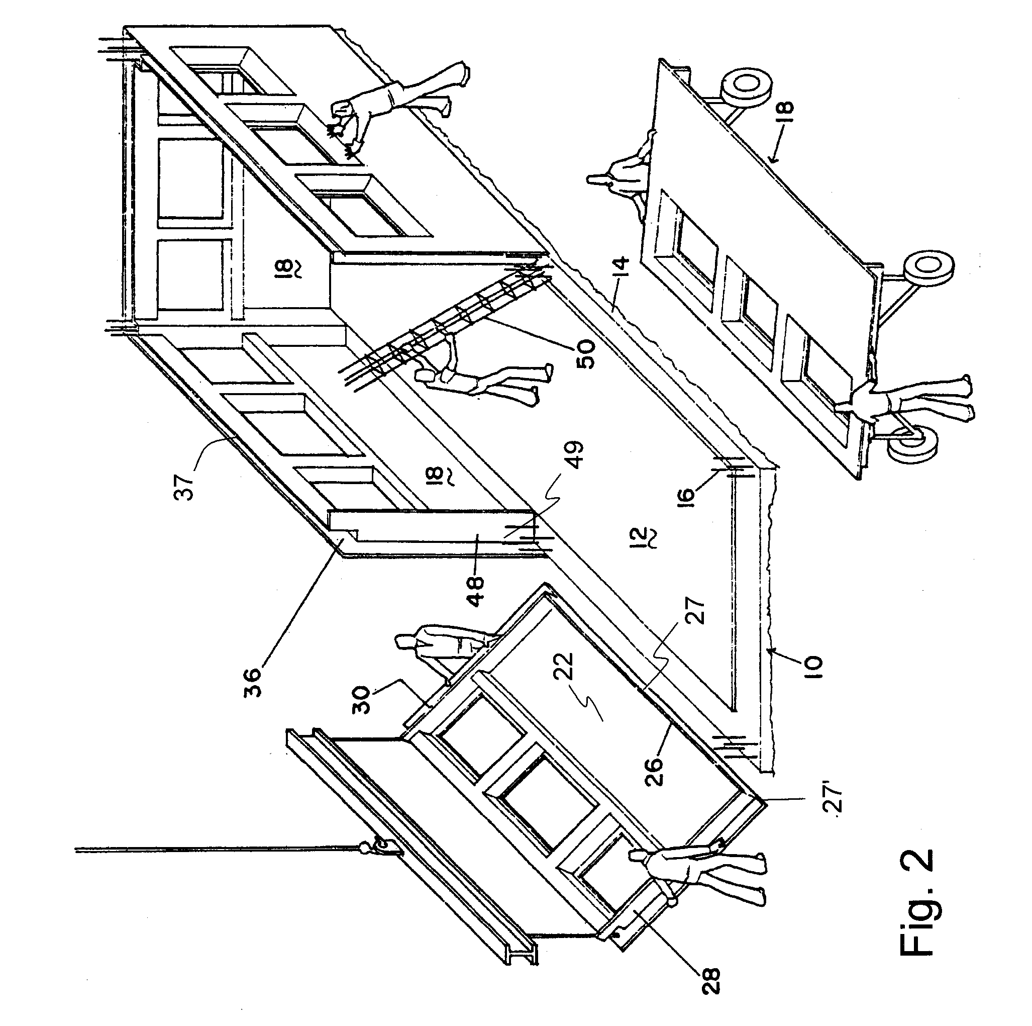
[0041]FIG. 2 illustrates assembly of the ground floor of a building using the construction system of the present invention. A plurality of pre-cast GRC wall panel 18 is assembled over foundation 10. Pre-cast GRC wall panel 18 includes a top perimeter 36, a first and second vertical perimeter 28 and 30, a bottom ...


PUM


Abstract

A permanent form building assembly includes one or more GRC forms having a one or more open cavities and a reinforcement structure. The GRC forms are designed and configured for a predetermined application. The reinforcement structure is inserted within the open cavities of the GRC forms prior to filling with concrete.

Description

BACKGROUND OF THE INVENTION[0001]1. Field of the Invention[0002]The present invention relates generally to building construction. Particularly, the present invention relates to a modular building assembly. More particularly, the present invention relates to a monolithic post and beam reinforced concrete structure using a system of permanent forms.[0003]2. Description of the Prior Art[0004]A common form of modern building construction is steel frame construction. Steel frame construction is relatively expensive due to the expense of the structural steel and the skilled labor involved. A less expensive method of construction is that of reinforced concrete construction. All reinforced building construction requires forms to mold the concrete into the different structural shapes required to carry the building loads. The forms create the voids where steel reinforcing rods are placed followed by filling with concrete in its fluid state, which is poured creating the structural components s...

Claims


Application Information

Patent Timeline
Patent Type & Authority Patents(United States)
IPC IPC(8): E04B2/00E04B1/16E04B5/36E04B5/38E04B7/10
CPCE04B1/165E04B7/102E04B5/38E04B5/36
Inventor MARTY, OSCAR
Owner MARTY OSCAR
Why Eureka
Try Eureka