
Automatic positioning marking pole

An automatic positioning and benchmarking technology, which is applied in the direction of educational appliances, instruments, teaching aids, etc., can solve the problems of unsafe use, long suspension time, large suspension swing, etc., to achieve safe and reliable use, short suspension time, and reduce The effect of amplitude

Inactive Publication Date: 2014-01-29
HUBEI WEIJIA TECH
View PDF4 Cites 3 Cited by
  • Summary
  • Abstract
  • Description
  • Claims
  • Application Information

AI Technical Summary

Problems solved by technology

[0004] Due to the large reaction force of the existing device, the swing of the suspension rod is large, the suspension rod takes a long time, and it is unsafe to use; the connection between the rod and the base is not strong due to insufficient pulling force, so the range of use is small

Method used


Image

  • Automatic positioning marking pole

Examples


Embodiment Construction

[0018] The present invention will be further described in detail below through specific embodiments in conjunction with the accompanying drawings.

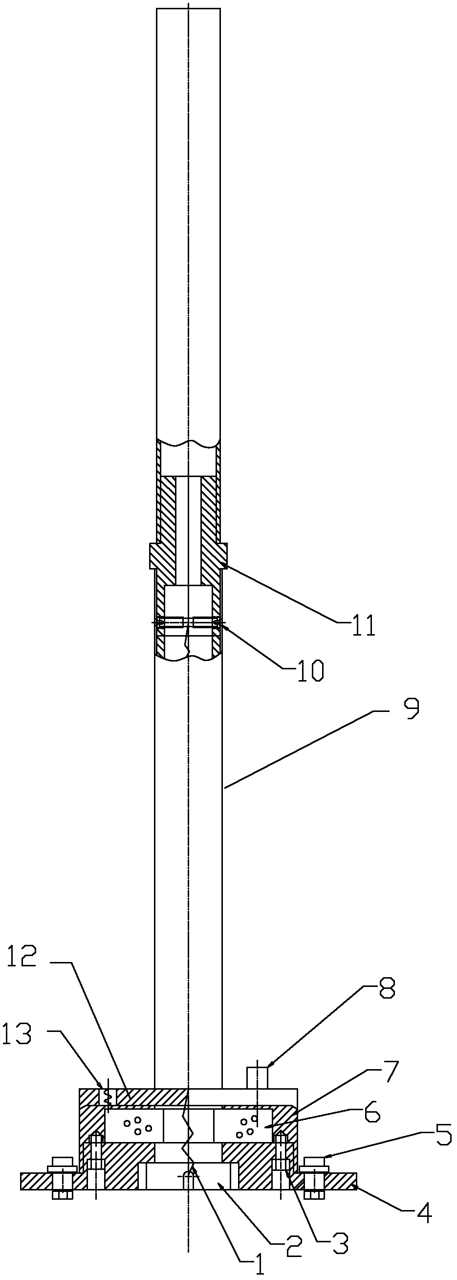
[0019] Please refer to figure 1 , the automatic positioning pole of the present invention, its main body comprises a base, a hollow rod body 9, a pole spring 1, a positioning plate 12, a shock-absorbing spring 13; one end of the pole spring 1 is connected with the base through a pull bolt 2, and the pole The other end of the spring 1 is extended and fixed to the inside of the hollow rod body 9; one end of the hollow rod body 9 is connected with the positioning disc 12, and the positioning disc 12 is connected with the end surface of the base, and the positioning disc 12 At least two positioning holes are opened on the end surface, and the vibration isolation spring 13 is arranged in the positioning hole, and the vibration isolation spring 13 is connected with the base.

[0020] Specifically, a spring bolt 10 is arranged inside th...


PUM


Abstract

The invention relates to an automatic positioning marking pole, wherein the main body of the marking pole body comprises a hollow marking pole, a marking pole spring, a positioning plate and a base, wherein one end of the hollow marking pole is connected with the positioning plate; the positioning plate is connected with an end surface of the base; one end of the marking pole spring is connected with the base after penetrating through the positioning plate; and the other end of the marking pole spring extends to and is fixed in the hollow marking pole. The automatic positioning marking pole is characterized by further comprising a shock-proof spring; at least two positioning holes are arranged on the end surface of the positioning plate; the shock-proof spring is arranged in the positioning hole; and the shock-proof spring is connected with the base. The marking pole is little in swing amplitude, short in rod stopping time, and safe and reliable in use.

Description

technical field [0001] The invention relates to an automatic positioning pole. Background technique [0002] At present, in the driver's pile test, some existing suspension rod automatic reset devices use magnets or pure spring devices on the upper part of the suspension rod, and some also install springs on the lower part of the rod. Just cause car body damage once, serious case, can cause car glass to break, personnel is injured. [0003] The existing device can only be hoisted on the gantry. Therefore, a single-arm and double-arm gantry must be equipped, which increases the investment cost, and the device can only be used in pile testing. [0004] The existing device has a large swing range of the suspension rod due to a large reaction force, a long time for stopping the rod, and is unsafe to use; the connection between the rod and the base is not strong due to insufficient pulling force, so the range of use is small. Contents of the invention [0005] The object of t...

Claims


Application Information

Patent Timeline
Patent Type & Authority Patents(China)
IPC IPC(8): G09B19/16
Inventor 王征平
Owner HUBEI WEIJIA TECH
Learn More