Device for separating ferromagnetic particles from a suspension

A technology of ferromagnetic particles and suspended matter, applied in magnetic separation, solid separation, chemical instruments and methods, etc., can solve problems such as discontinuity

Inactive Publication Date: 2011-10-12
SIEMENS AG
View PDF8 Cites 4 Cited by
  • Summary
  • Abstract
  • Description
  • Claims
  • Application Information

AI Technical Summary

Problems solved by technology

Although the separation can be efficiently carried out, the separation method can only be carried out intermittently, since the reactor must be opened and the ferromagnetic particles removed after a defined amount of ferromagnetic particles has accumulated

Method used


Image

  • Device for separating ferromagnetic particles from a suspension
  • Device for separating ferromagnetic particles from a suspension

Examples


Embodiment Construction

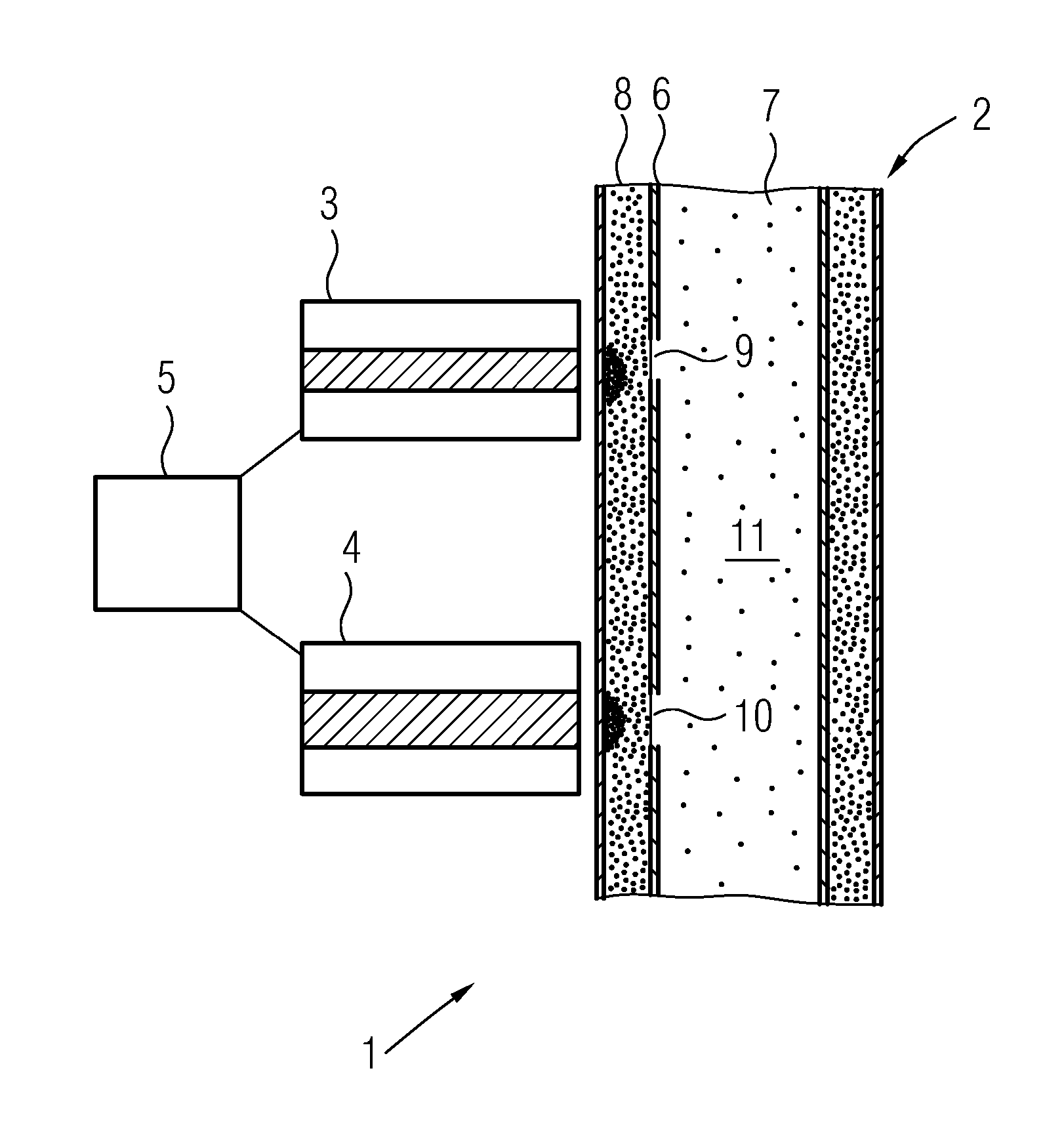
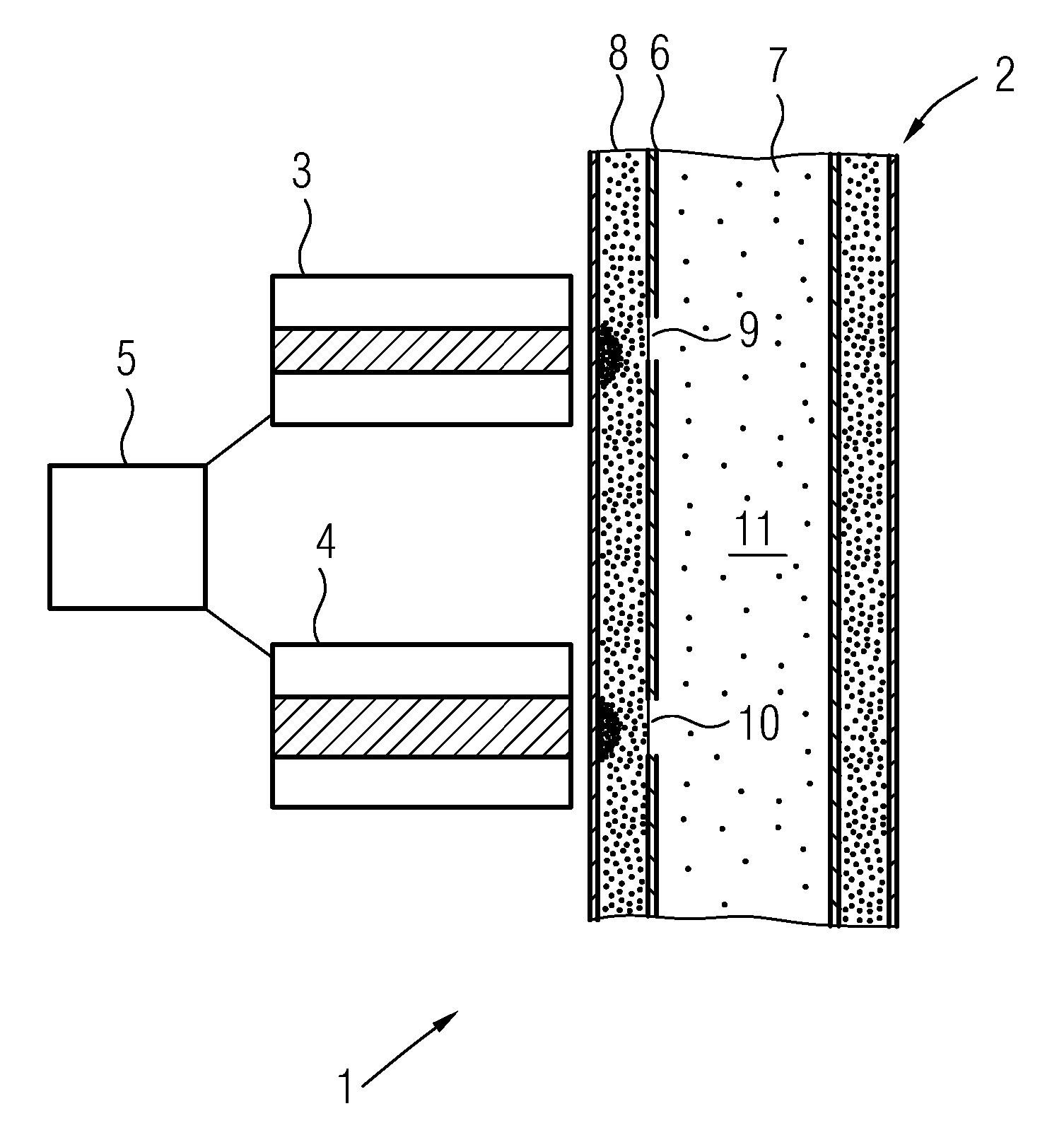
[0019] The device 1 comprises a reactor 2, on the outside of which magnets 3, 4 are arranged. This is an electromagnet which can switch the flow on and off by means of the controller 5 .

[0020] The reactor 2 comprises an insert 6 which, in the exemplary embodiment shown, is of tubular design. The reactor 2 is likewise designed as a tube or a cylinder. The insert 6 in the reactor 2 separates an inner cavity 7 inside the insert 6 from an outer cavity 8 , which has a circular cross-section and is bounded by the outer wall of the reactor 2 .

[0021] The insert 6 has a plurality of openings 9 , 10 spaced apart from one another, through which the inner chamber 7 and the outer chamber 8 are connected. The opening 9 is located near the magnet 3 and the opening 10 is located near the magnet 4 . In other exemplary embodiments there may be further openings which are either distributed over the circumference of the insert 6 and / or are arranged distributed in the longitudinal directi...


PUM


Abstract

Device for separating ferromagnetic particles from a suspension, having a reactor (2) through which the suspension can flow, with at least one magnet (3, 4) arranged on the outside of the reactor (2), wherein the reactor (2) has an interior space (7) and an exterior space (8) surrounding the former, wherein the interior space (7) and exterior space (8) are separated from one another by an insert (6), and the insert (6) has at least one opening (9, 10) near the at least one magnet (3, 4).

Description

technical field [0001] The invention relates to a device for separating ferromagnetic particles from a suspension, which has a reactor through which the suspension can flow, with at least one magnet arranged on the outside of the reactor. Background technique [0002] In order to obtain the ferromagnetic components present in the ore, the ore is ground into a powder and the powder present is mixed with water. The suspension is exposed to a magnetic field generated by one or more magnets, thereby attracting the ferromagnetic particles, whereby the ferromagnetic particles can be separated from the suspension. [0003] DE 27 11 16 A discloses a device for separating ferromagnetic particles from a suspension, in which a roller consisting of iron bars is used. As the drum rotates, the iron bars are alternately magnetized so that the ferromagnetic particles adhere to the iron bars, whereas the other components of the suspension fall between the iron bars. [0004] DE 26 51 137 A...

Claims


Application Information

Patent Timeline
Patent Type & Authority Applications(China)
IPC IPC(8): B03C1/28
CPCB03C1/288B03C2201/18
Inventor V·达诺夫B·格罗莫尔
Owner SIEMENS AG
Why Eureka
Try Eureka