Air intake arrangement for an aircraft

A technology of aircraft and equipment, which is applied in the field of air intake equipment, can solve the problems of reducing the service life and efficiency of equipment, and achieve the effect of minimizing the performance reduction of aircraft

Inactive Publication Date: 2011-10-12
AIRBUS OPERATIONS (SAS)
View PDF2 Cites 3 Cited by
  • Summary
  • Abstract
  • Description
  • Claims
  • Application Information

AI Technical Summary

Problems solved by technology

However, microcracks can appear on the structure of the profile, especially where it is fixed to the elastic sheet, mainly due to the high pressure exerted on the profile and the high velocity of the air flow, which can significantly reduce the use of the device life and efficiency

Method used


Image

  • Air intake arrangement for an aircraft
  • Air intake arrangement for an aircraft
  • Air intake arrangement for an aircraft

Examples


Embodiment Construction

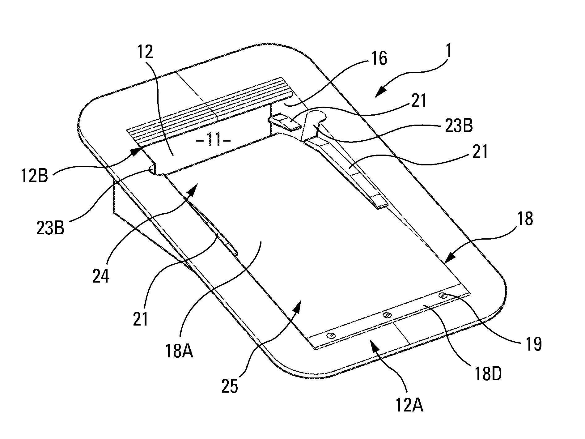
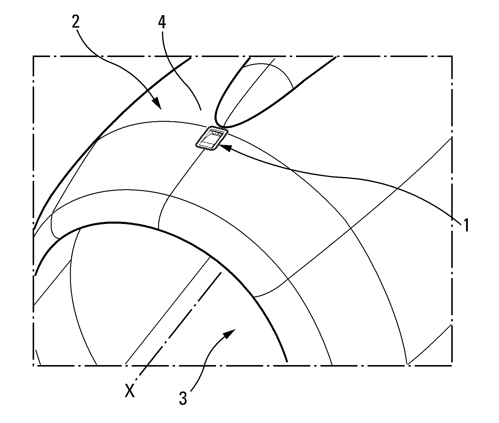
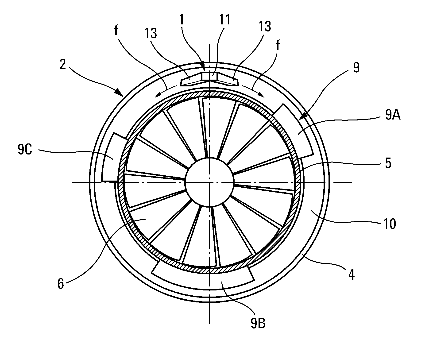
[0032] exist figure 1 and figure 2 The air intake device 1 according to the invention shown in FIG. 1 is arranged in a nacelle 2 of an engine mounted on an aircraft (not shown).

[0033] Such as Figure 1 to Figure 3 As shown schematically, the nacelle generally comprises: a front air intake section 3 for supplying air to the engine; a middle section 4 surrounding an outer casing 5 of the engine's compressor and blower 6; and a rear section 7 , which surrounds the turbine and combustion chamber, from which the outer casing of the tailpipe 8 and its cone emerge.

[0034] Various mechanical and / or electrical devices or equipment 9 are attached to the outer casing 5 of the blower 6 and compressor, ie in the annular enclosure 10 between the outer casing 5 of the engine and the nacelle 2 . exist figure 2 Some of the devices 9 arranged in said area 10 are schematically shown in , namely the full authority digital engine control device 9A, the auxiliary relay box 9B and the eng...


PUM


Abstract

The invention relates to an arrangement (1) that comprises a mobile plate (18) controlled by a means for fluid communication (23) between the outer (18A) and inner surfaces of the mobile plate (18), wherein said means is located at least in the vicinity of a limited downstream area (24) of said outer surface (18A), are at a high pressure when the aircraft flies at cruising speed, and are capable of transmitting said high pressure to an extended area (26) of said inner surface.

Description

technical field [0001] The invention relates to an air intake device for an aircraft, comprising a ventilation channel with an air intake opening. Background technique [0002] It is known that such air intake devices are used extensively in the aviation sector for renewing the air in enclosed areas containing hazardous ambient media of the flammable or explosive type and / or heat-sensitive materials, It is necessary for them to ensure continuous ventilation of the area in order to avoid any risk of failure of the material or of accidents in the vicinity. [0003] This is especially the case for the plurality of mechanical and / or electrical devices arranged in the annular enclosure between the outer casings of the compressors and blowers of the aircraft turbojet and the nacelle. Said devices, such as the Full Authority Digital Engine Control (Full Authority Digital Engine Control in English), the auxiliary relay box (Gearbox in English), the engine oil container, the fluid p...

Claims


Application Information

Patent Timeline
Patent Type & Authority Applications(China)
IPC IPC(8): B64D33/08
CPCB64D2241/00B64D33/08Y10T137/0536
Inventor A·波特E·尚瑟雷勒F·阿尔瓦雷D·普拉
Owner AIRBUS OPERATIONS (SAS)
Why Eureka
Try Eureka